Circuit Descriptions, Abbreviation List, and IC Data Sheets
EN 200 JL2.1E AA9.
9. Circuit Descriptions, Abbreviation List, and IC Data Sheets
Index of this chapter:
9.1 Introduction
9.2 LCD Power Supply
9.3 DC/DC Converters (on SSB)
9.4 Inputs
9.5 MPIF (PNX 3000)
9.6 PNX2015
9.7 PNX2015: AVIP
9.8 PNX2015: Columbus (Comb Filter)
9.9 PNX2015: HD Subsystem
9.10 PNX2015: LVDS Transmitter (if used)
9.11 PNX2015: Stand-by Processor
9.13 VIPER 2 (PNX 8550)
9.14 MOP
9.15 Ambient Light (if present)
9.16 Abbreviation List
9.17 IC Data Sheets
Notes:
•Only new circuits (circuits that are not published recently)
are described.
• Figures can deviate slightly from the actual situation, due
to different set executions.
• For a good understanding of the following circuit
descriptions, please use the wiring, block (chapter 6) and
circuit diagrams (chapter 7). Where necessary, you will find
a separate drawing for clarification.
9.1 Introduction
This chassis (development name “Jaguar “) is: The move from
the analog world to the digital world. W.o.w. from signal
processing via "hardware circuits" to signal processing via
"software algorithms". This means: no software = no picture
and sound!
Some key components are:
• MPIF (PNX3000).
• AVIP/COLUMBUS (PNX2015).
• SPIDER.
• VIPER 2 (PNX8550).
• MOP (EPLD).
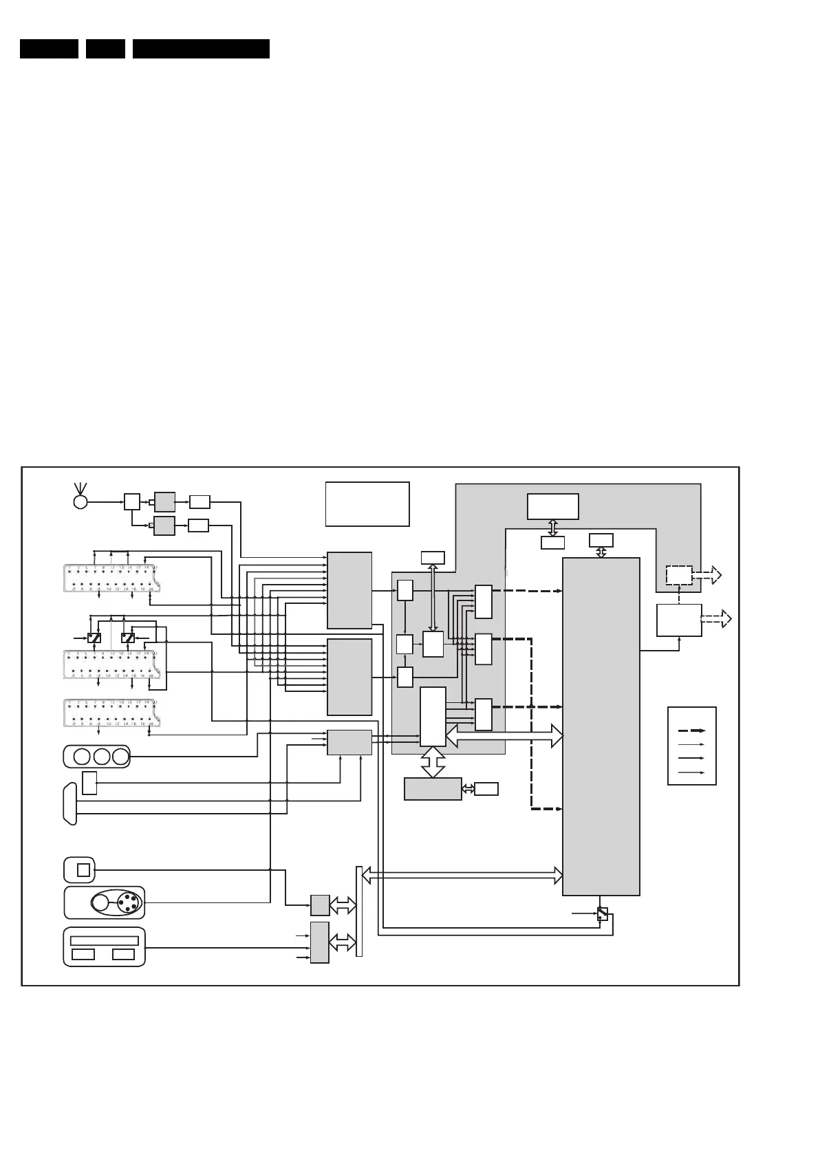
9.1.1 Chassis Block Diagram
Figure 9-1 Video Block Diagram
F_15710_177.eps
260905
HDMI
Standby
µProcessor
YC_Comb
CV BS-IF
CV BS1
CV BS2
CV BS3/Y C3
CV BS4/Y C4
I
2
D
CV I1
CV I2
MPIF
Main
MPIF
Sec
YC_Comb
CV BS-IF
CV BS1
CV BS2
CV BS3/Y C3
CV BS4/Y C4
CV I1
CV I2
DV 1
DV 2
DV 3
X
I
O
/
P
C
I
B
u
s
USB
2.0
Ether
net
LAN
Portable Memory
(free)
Selection by
Tri-State
XIO/PCI Bus
Main Video Out
Spider
Viper II
Tunnel
Inter f ac e
PNX
2015
SDRAM
SDRAM
Flash
DDR
LVDS
to
Display
LVDS
Transm.
External
Input Sources
Splitter
Analog
SAW
Analog
SAW
Main
Analog
Tuner
Antenna
(free)
Sec
Analog
Tuner
Colum-
bus
AVIP
Main
DV4
DV5
AVIP
Sec
DV 1
DV 2
DV 3
Switch
AVIP1
AVIP2
VO-1
Columbus
VO-2
AVIP1
AVIP2
VO-1
(656/Y)
Columbus
VO-1
VO-1
VO-2
VO-2
HD
Sub
syst e m
Tunnel
Tunnel
MOP
Rec Video Out
(DENC)
I/O 8
CVBS/YC Out
(Scart 2)
CVBS Terr Out
TS Out
CVBSTerr Out
BL2.1E
(Full Jaguar 2
nd spin)
Video Signal Flow
V2. 3
LAN
RJ
45
LAN
HDMI
DVI-I (analog RGB)
CVBS/Y/C -AV2
CV BS-A V1
CV I-A V1/3
CVI-AV2/4
SCART 2
SCART 1
FBL1
FBL2
G2
Cin
CVBS2/Yin
B1
G1 R1
CVBS1
Cout
B2
R2
FBL2FBL2
DVI
CVBSTerr Out
CVBS/Y/C-Side
SCART 3
Status 3
CV BS 3
Y
Pb
Pr
AV 4
Status 2
Status 1
Rec -Out
SD/HD CVI
Rec Out
(Scart 1)
DV I-D
Tri-Stateable
Signal Lines
Control
Lines
Signal
Lines
Legend
Unused
Lines
Memory Slot
USB 2
USB 2
Analog Tuner-IF Main
CVBS-AV1
CVBS-AV3
Y/C-AV1
CVBS/Y/C-AV2
CVBS/Y/C-Side
CV I-A V1/3
CVI-AV2/4
CVBS-AV1
CVBS-AV3
Y/C-AV1
CVBS/Y/C-AV2
CV BS/Y /C-Side
CV I-A V1/3
CV I-A V2/4
Analog Tuner
-IF Sec
SIDE
CV
BS
Hirate
CV I1
CV I2
HDMI#1HDMI#2
CV I3
(656/Y)
(656/Y)
(UV)
I
2
D