Circuit Descriptions, Abbreviation List, and IC Data Sheets
EN 219JL2.1E AA 9.
de-interlacing and scaling tasks. It reads images from memory,
performs a transformation, and writes the result back in
memory.
The MBS main features are:
• De-interlacing using either a median, 2-field majority
select, or 3-field majority select algorithm with an edge
detect/correct post-pass (these three provide increasing
quality, at expense of increased bandwidth).
• Edge detect/correct on an input frame that has been
software de-interlaced (this provides future capabilities in
case we develop a better core de-interlacer than 3-field
majority select).
• Horizontal and vertical scaling (on the input image, or on
the result of edge detect/correct stage).
• Linear and non-linear aspect ratio conversion.
• Anti-flicker filtering.
• Conversions from any input pixel format to any non-
indexed pixel format, including conversions between 4:2:0,
4:2:2 and 4:4:4, indexed to true colour conversion, colour
expansion / compression, de-planarisation / planarisation
(to convert between planar and packed pixel formats),
programmable colour space conversion.
Supported video measurement functions during scaling or de-
interlacing pass:
• Gather a histogram of luminance values (this data is used
by software to control histogram modification).
• Measure noise level inside a rectangular window.
• Measure the lowest level luminance within a rectangular
window (used to control black stretch in QVCP).
• Measure UV bandwidth inside a rectangular window.
QTNR (Quality Temporal Noise Reduction and Video
Measurement)
The QTNR block has two primary functions: Temporal Noise
Reduction: reading two video fields from memory, "current"
(noisy) and "previous" (noise reduced) and producing a noise-
reduced version of "current" in memory. While doing this, or as
a separate "measurement only" pass, perform video
measurements:
• Gather a histogram of luminance values (this data is used
by software to control histogram modification).
• Measure noise level inside a rectangular window.
• Measure the lowest level luminance within a rectangular
window (used to control black stretch in QVCP).
• Measure UV bandwidth inside a rectangular window.
• Measure the position of top and bottom black bars in the
image.
QVCP (Quality Video Composition Processor)
The PNX8550 contains two QVCPs, which are responsible for
combining and displaying video and graphics images from
main memory. The primary QVCP serves as the main display
pipeline, the second one is targeted to be connected to a record
device (VCR). The primary QVCP allows composition of up to
five layers, and can output in ITU-656/HD/VGA format in 10 bits
per component up to 81 Mpix/s.
The secondary QVCP allows composition of up to two layers,
can output in 656 10-bit component mode up to 81 MHz (40.5
Mpix/s). The secondary QVCP is connected to an on-chip
Digital Video Encoder (DENC), allowing direct analog CVBS or
S-video output.
In analog output mode, standard definition interlaced NTSC or
PAL is supported (SCART2-out signal, for VCR-recording).
The encoder has two DACs. DAC1 provides CVBS or
luminance for S-video. DAC2 provides chrominance for S-
video.
Internal sensors allow software to test loading on the S-video
Chrominance line to decide whether to output luminance or
CVBS on DAC1.
The primary and secondary QVCP each contain a series of
layers and mixers. The QVCP creates a series of display data
layers (pixel streams) and mixes them logically from back to
front to create the composite output picture.
Some of the features the QVCP provides are:
• Video Quality Enhancement.
• Luminance Transient Improvement.
• Colour Dependent Sharpening.
• Horizontal Dynamic Peaking.
• Histogram Modification.
• Digital Colour Transient Improvement.
• Black Stretch.
• Skin Tone Correction.
• Blue Stretch and Green Enhancement.
• Video and Graphics horizontal up scaling.
• Colour space unification of all the display surfaces.
• Contrast and Brightness Control.
• Screen timing generation adopted to the connected display
requirements (SD-TV standards, HD-TV standards,
progressive, interlaced formats).
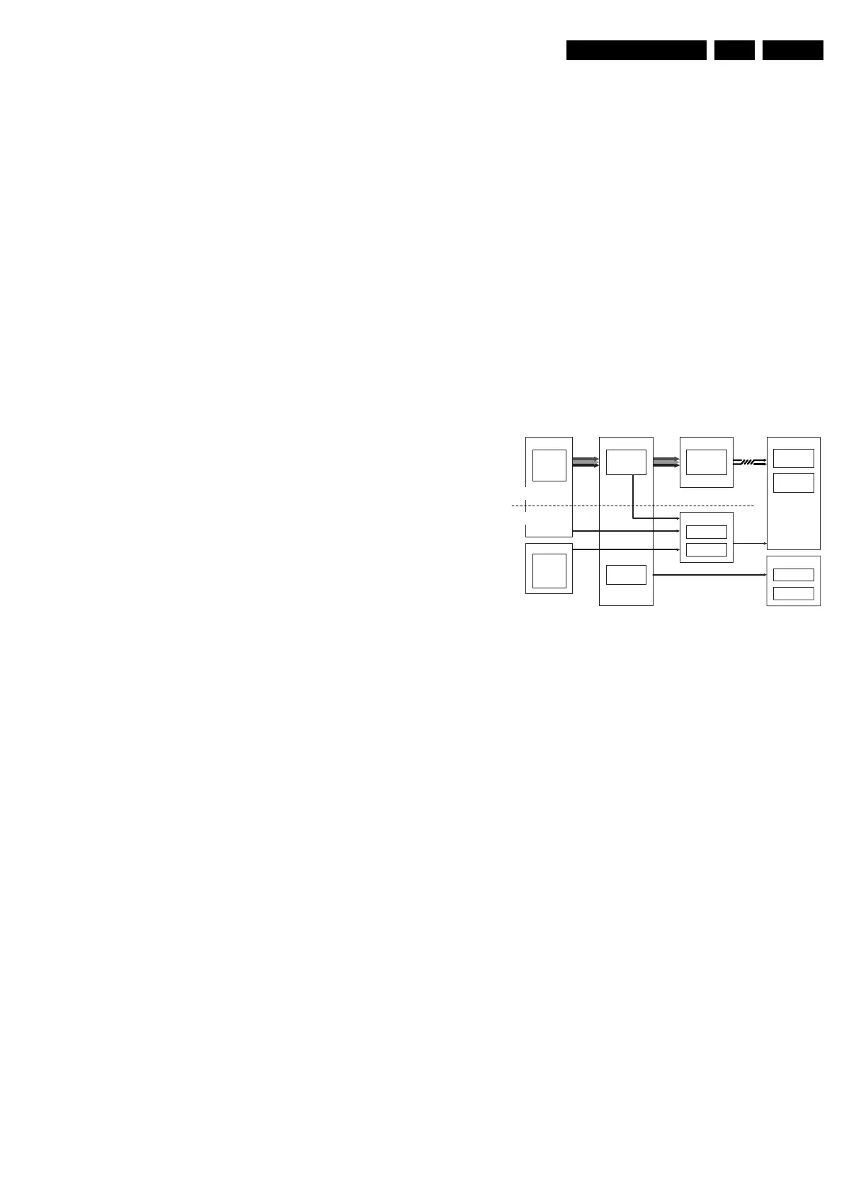
9.14 MOP
Figure 9-34 Block diagram of video output with MOP
In this chassis an EPLD (or MOP) is used for AmbiLight
processing and for some picture enhancements, like blue and
green stretch.
Ambi-light
Display
MOP
LVDS
LCD
PDP
Display CTRL
Module Left
PNX2015
Stand-by
µP
VIPER
QVCP
5L
Ambi-light
PNX2015
LVDS Tx
Suppl y
I2C4
Module Right
Video
LVDS
Control
Signals
RGB
Control
Signals
Video-F low
CTRL-flow
RGB
V Sync
F_15400_012.eps
300505