Circuit Descriptions, Abbreviation List, and IC Data Sheets
EN 203JL2.1E AA 9.
9.2 LCD Power Supply
9.2.1 General
•All displays:
– The sound supplies are +/- 18V.
– A loudspeaker DC protection is added (via TS7030 on
the Main Supply).
– A POK (Power OK) is generated when the 12V from
the Aux supply is stabilised.
– The STANDBY supply is integrated on the Audio
Amplifier panel.
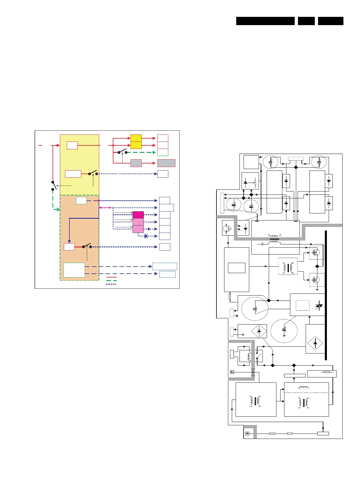
9.2.2 Block Diagram
Figure 9-5 Block diagram power supply
Main Supply
Diversity
• Mains input voltage:
– 240 V
AC
.
• Mains filter diversity:
– 2 x mains filter + inrush current resistor.
• Screen size diversity:
– One module for 32" and 37” sets.
– Two (almost identical) modules on one PWB for 42"
sets.
Specifications
• 12 V / 3 A on connector 1304 (for AmbiLight and to
generate +8V6).
• 24 V / 5 A for LCD backlight on connector 1304.
• +18V, -18V sound on connector 1M02.
• +8V6 (derived from +12V from the Main Supply, switched
"off" in stand-by).
• Output voltage: over-voltage protection of resonant supply.
• Output current protection of resonant supply.
• Current protection at some safety fault conditions.
Stand-by Mode
• The resonant supply is switched "off" via a relay (1350 or
1450) that is driven by the Stand-by Supply (via connector
1305).
Outputs
• 130-400 V
DC
(full range) to Stand-by Supply (connector
1306).
• Mains over-voltage and safety protection for Stand-by
Supply (connector 1307).
Inputs
• Relay drive voltage (for STANDBY/ON mode) on
connector 1305.
• DC_PROT signal to protect loudspeakers when there is a
DC voltage across the loudspeakers (1M02).
Figure 9-6 Functional diagram Main Supply (one module)
F_15710_184.eps
260905
Standby Supply
Main
Supply
+5V2
+5V2S
1V2
3V3
3V3Stb
1V2Stb
Standby
+8V6
STANDBY
+8V6
+12VS
+12VS
+1V2
+1V2
+12VSW
+2V8
+2V8
+3V3
+3V3
+2V5
Enable-3V3
Enable-2V8
En ab le - 1V 2
+12V or +24V
and Vsound
Display Inverter
+12V/24V
+VSound
+5V2
+33V tuner
STANDBY
+33V
+2V5D (DDR)
+2V5
Mains
STANDBY
available from standby onw ards
available from semi-standby onw ards
available from on onwards
1
+400V
AVS10
Mains filter
Mains filter
Mains Harmonic
Inruch
Bridge
Rectifier
US / APmulti
US / APmultiEUR / CHINA
EUR / CHINA
Relais
1308
1305
Driver Trafo
US / APmulti
Heatsink
Doubler
Control supply
MC34067P
Resonant Trafo
Heatsink Heatsink
Opto
12V
24V
-18V18V 1M02
Reference
COLD
HOT
+12V
1306
1307
Bridge
Rectifier
1304
+12V
+24V
HOT
HOT
COLD
COLD
GND_AUD
Audio Supply
Display supply
Mains input
Stand By supply
Supply
Invertors
(RES)
DC prot
25V_HOT
(Startup)
Relais drive
GND_SND
+400V
+400V
E_14620_025.eps
100504