Circuit Descriptions, Abbreviation List, and IC Data Sheets
EN 215JL2.1E AA 9.
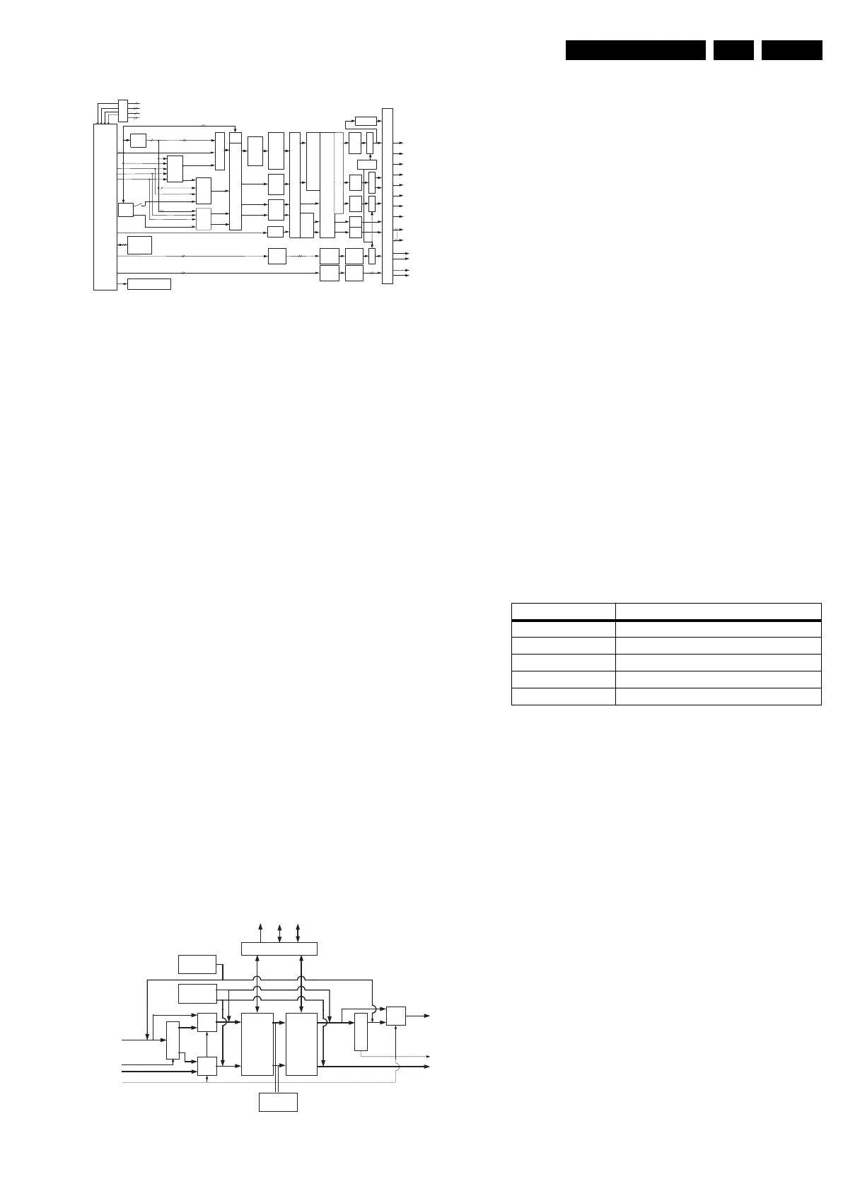
Audio Processing
Figure 9-26 Audio processing block diagram
Main features are:
• Master volume control and Balance.
• Tone control (Loudness, Bass, Treble, Equalizer).
• Dolby ProLogic delay.
• Incredible Mono and Stereo.
• Virtual Dolby Surround (VDS 522, 523).
• Virtual Dolby Digital (VDD 522, 523).
• Digital audio I/O interface (stereo I2S input interface).
• Eight audio DACs for six channel loudspeaker outputs and
stereo headphones output.
• Audio DACs for stereo SCART output and stereo LINE
output.
• Serial data link interface for interfacing with the analog
multi-purpose interface IC PNX3000 (MPIF).
9.8 PNX2015: Columbus (Comb Filter)
9.8.1 Introduction
This block provides the following picture improvement
functions:
• Enhanced 2D combing for PAL and NTSC.
• 3D field combing for PAL and NTSC.
• 3D frame combing for PAL and NTSC.
• Spatial noise reduction for all component video standards.
• Temporal noise reduction for all component video
standards.
The comb filter is controlled via a separate I
2
C interface on the
PNX2015, this is to ensure registers containing measurement
information, are accessed at appropriate times. The
measurement information is also available as ancillary data
within the video stream (ITU-656).
For certain features of the comb filter, access to external
memory is required. The PNX2015 has a unified memory that
both comb filter and HD subsystem’s share concurrently.
9.8.2 Block Diagram
Figure 9-27 COLUMBUS internal block diagram
Figure above, shows a block diagram of the Columbus comb
filter in the PNX2015 device. An input video signal is supplied
by the AVIP and fed to the Columbus block. The signal is
supplied in digitized components of:
• CVBS or Y.
• Uncombed U.
• Uncombed V.
The CVBS signal is combed, extracting the luminance
components and rejecting the chroma components. The UV
signals are combed, rejecting the left over luminance
components, from a previous filtering (normally band pass
filtered).
The outputs from the 3D comb filter are:
• Combed luminance signal (Y).
• Combed U signal.
• Combed V signal.
The output from the 3D comb filter feeds the SWAN and LORE
noise reduction block, which performs spatial/temporal noise
reduction, for both luminance and chrominance components.
Control Register Interface
The control registers are accessed via I
2
C. Most signals that
can be written via I
2
C are double buffered. The fast I
2
C
interface implemented on the COLUMBUS is a 5V compliant,
400 kHz slave receiver/transmitter. The I
2
C will not be blocked
during voltage shorts or opens.
For the system dependent parameters of the 3D-Comb filter,
five register banks are present. Data can be written in one of
the banks via I
2
C, by programming bits [2:0] of the
SYSTEM_SELECT register. The bits [6:4] of the
SYSTEM_SELECT register select, which register bank is used
by Columbus to define the filter settings.
Internal Test Generators
There are two test generators inside the COLUMBUS chip:
• The "656 test generator" generates a 656 compliant stream
and is used for testing the functionality of the 656 encoder
and decoder. The 656 stream can be injected at the front
end or the back end of the chip.
• A second internal test pattern generator enables testing of
the device and attached external memory (if present). The
test pattern generator signal can be inserted at the front
end of the chip (passing through the 3D Comb and noise
reduction system and external memory) or at the back end
of the chip. Test patterns are available for both PAL/
SECAM and NTSC systems.
9.9 PNX2015: HD Subsystem
The HD subsystem performs MPEG video decoding on HD/SD
transport streams. It interfaces with the PNX8550 (VIPER) and
video co-processor (SPIDER) via tunnel interfaces, HD/SD
using DV4 and DV5 inputs, and PNX8550 using DV1, DV2 and
DV3 outputs. The HD subsystem can also perform a range of
video measurements on a transport stream.
+
L, RSUBC
Master Volume & Trim
OFF/ I-Mono /
I-Stereo
MAIN
Ba/Tr
or EQ
Loudn.
or
BBE
®
Bass Management
Delay
Digital Output Crossbar
C
Ba/Tr
or EQ
Loudn.
Ls/Rs
Ba/Tr
or EQ
L,R
SM
AUX1
Ba/Tr
AUX1
Vol /Trim
AUX1
SM
AUXx
Vol /Trim
AUXx
SM
Noise/
Silence
Gen.
(L+R)/2
SUB
SM
C
SM
Ls
SM
+
DAFO1
I
2
S1L,R OUT
to
I
2
S6L,R OUT
MAIN
C
Ls
AUX1/ HP
AUX2,3,4,5,6
5 equal channels for I
2
S, DAC1, DAC2
C IN
S/Ls IN
L,R
Audio Monitor
Level Adj.
AUX2-6
Digital Input Crossbar ( SSel, Matrix )
AUX1
MAIN
Rs IN
L,R
LFE
Rs
LsRs
LsRs
Rs
SM
+
SW Filter
Beeper
6
DAFO2
DAFO3
DAFO4
DAFO5
DAFO6
DAFO7
DAFO8
DPL II
®
DUB or DBE
in L,R or SUB
Hall/
Matrix
L,R,C,Ls,Rs (DPL II)
5
Automatic Volume Leveling
C
S/Ls
Rs
LFE
AVL
Contr.
Acoustical Compensation
DEC (L/A,R/B, Mono, SAP)
PIPMONO
ADC (L/A, R/B)
I2S IN 1 to 6
Level
Adj.
VIRT
VDS
®
522,523
VDD
®
522,523
MAIN MSel
C
MSel
S,Ls
Rs
MSel
L,R (DPL II)
L,R (M,ST, 5.1)
L,R (M,ST, 5.1)
C (DPL II)
C IN
C Hall/Matrix
(L+R)/2
C VIRT
L,R VIRT
Ls,Rs (DPL II)
S/Ls IN
S Hall (L+R)/2
S Matrix (L-R)/2
Rs IN
DAC2
L,R
DAC1
L,R
E_14700_075.eps
250505
Memory Interface
3D Comb
PAL & NTSC
Local Regression
&
SWAN 3D
Noise Reduction
656 Decoder
656 Encoder
Pattern
Test
Generator
Y/CVBS
UV
UV (ITU656)
Y (ITU656)
Noise
Measurement
SEL656
Mux Mux
Mux
SEL656
WEB/DAVB
WEA/DAVA
DQ(16:1)
A(11:0)CONTROL
656
Test
Generator
E_14700_083.eps
300505
Bank number System
0 PAL B, G, H, I, D, K
1 PAL M
2 PAL N
3NTSC
4 Bypass