Circuit Descriptions, Abbreviation List, and IC Data Sheets
EN 209JL2.1E AA 9.
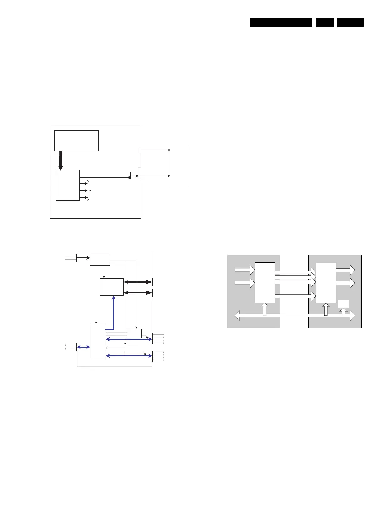
9.4 Inputs
9.4.1 USB
This chassis features USB2.0. It is hosted by a separate IC
(7N00, diagram B13A) which communicates with the VIPER
via a PCI bus.
Each USB port has four lines:
1. 5V (red).
2. D- (white).
3. D+ (green).
4. GND (black).
Figure 9-13 USB configuration
Figure 9-14 Multimedia card reader assy
USB2.0
A tandem USB connector (1H01) is mounted on the SSB, on
which you can connect two USB devices (each port has a D+
and D- line; this is the differential signal path for USB); one
device (hub) is the card-reader; only USB mass storage class
device is supported, so other USB devices (card-readers) have
to be compliant with this class.
The host (= SSB) needs to provide the power supply (coming
from the Stand-by Supply) to the attached devices (like
memory cards or other USB devices). Since it is not known
what the customer will attach (e.g. a USB hub with multiple
USB devices), and these USB devices draw current from the
SSB, these supply lines must be protected against over-current
and/or too many connected devices. Upon detecting an over-
current condition, the hub device reports the over-current
condition to the host and disables the power supply to the
downstream port. This protection is done on a per-port basis.
There are two downstream USB ports where the customer can
attach bus-powered devices, two card slots and internal logic
that needs power. So, the card reader is a self-powered device
with a separate power connection (max. 1900 mA):
• Downstream USB port A: max. 500 mA
• Downstream USB port B: max. 500 mA
• Media interface: max. 500 mA
9.4.2 HDMI
Introduction
Note: Text below is an excerpt from the”HDMI Specification”
that is issued by the HDMI founders (see http://www.hdmi.org).
This High-Definition Multimedia Interface is developed for
transmitting digital television audiovisual signals from DVD
players, set-top boxes and other audiovisual sources to
television sets, projectors and other video displays.
HDMI can carry high quality multi-channel audio data and can
carry all standard and high-definition consumer electronics
video formats. Content protection technology is available.
HDMI can also carry control and status information in both
directions.
As shown in the HDMI block diagram, the HDMI connector
carries four differential pairs that make up the TMDS
(Transition Minimized Differential Signalling) data and clock
channels. These channels are used to carry video, audio, and
auxiliary data. In addition, HDMI carries a VESA DDC channel.
The DDC is used for configuration and status exchange
between a single source device and a single sink device.
Figure 9-15 HDMI block diagram
Audio, video, and auxiliary data is transmitted across the three
TMDS data channels. The video pixel clock is transmitted on
the TMDS clock channel and is used by the receiver as a
frequency reference for data recovery on the three TMDS data
channels.
Video data is carried as a series of 24-bit pixels on the three
TMDS data channels. TMDS encoding, converts the 8 bits per
channel into the 10 bit DC-balanced transition minimized
sequence, which is then transmitted serially across the pair at
a rate of 10 bits per pixel clock period.
Video pixel rates can range from 25 MHz to 165 MHz. Video
formats with rates below 25 MHz (e.g. 13.5 MHz for 480i/
NTSC) can be transmitted using a pixel-repetition scheme. The
video pixels can be encoded in either RGB, YC
B
C
R
4:4:4, or
YC
B
C
R
4:2:2 formats. In all three cases, up to 24 bits per pixel
can be transferred.
In order to transmit audio and auxiliary data across the TMDS
channels, HDMI uses a packet structure. In order to attain the
higher reliability required of audio and control data, this data is
protected with a BCH error correction code and is encoded
ISP1561
Card
Reader
USB
cable
power
cable
VIPER
PCI
USB 2.0
HOST
Not used
USB A
conn
Card
Reader
USB
cable
5V
power
cable
USB 2.0
F_15400_108.eps
250505
USB 2.0 slot A
POWER
+5V
GND
USB 2.0
D+
D-
USB
2.0
HUB
media
interface
SUPPLY
protec
tion
prote
ction
5
V
5
V
enable
overcurrent
overcurrent
enable
Card slot 0
Card slot 1
CF I, CFII, MD
MS, MSpro, SD,
MMC, SM, xD
USB 2.0 slot B
+5V
D -
D +
GND
+5V
D -
D +
GND
USB
2.0
USB 2.0
USB 2.0
USB
2.0
Cardreader USB 2.0
F_15400_109.eps
180505
HDMI SinkHDMI Source
Video
Audio
Video
Audio
TMDS Channel 0
TMDS Channel 1
TMDS Channel 2
E_13950_062.eps
120304
Transmitter
Receiver
TMDS Clock Channel
Display Data Channel (DDC)
EDID
ROM