Circuit Descriptions, Abbreviation List, and IC Data Sheets
EN 211JL2.1E AA 9.
9.5 MPIF (PNX 3000)
9.5.1 Introduction
The MPIF (Multi Platform InterFace, type number PNX3000,
item number 7C00) is an analogue video and audio pre-
processing unit for the AVIP TV processor. It contains the high
frequent IF part and all the analog video and audio source
switching for external in- and outputs. The MPIF can handle
CVBS, Y/C, RGB (1fH/2fH) and YPbPr (1fH/2fH) video signals
as well as stereo, I
2
S, and second sound IF audio signals. The
MPIF converts the selected video and audio streams from the
analog to the digital domain. Via three high-speed serial data
links (I
2
D), the digitized audio and video signals are streamed
(594 Mbit/s) to the AVIP IC for further processing.
The MPIF uses a clock coming from the AVIP of 13.5 MHz
(CLK_MPIF) and is I
2
C driven. The supply voltage for the MPIF
is 5V.
The MPIF uses the following input signals:
• CVBS, Y/C, YPbPr, or RGB video format.
• 1fH or 2fH video.
• Clock 13.5 MHz from the AVIP.
•I
2
C from the VIPER.
• Clamping-pulse from the AVIP.
9.5.2 Block Diagram
Following figure shows the MPIF block diagram:
Figure 9-17 MPIF block diagram
9.5.3 IF Processing
The MPIF is capable of demodulation of RF signals.
Analogue Vision IF Processing
Some specifications:
• Synchronous demodulation of the IF vision carrier.
Selectable frequency and auto-calibration of the VCO
(Voltage controlled oscillator).
• Group delay correction for BG system.
• AGC at vision IF level to give fixed CVBS output level, and
AGC at RF level (tuner AGC) to limit output level of the
tuner.
• AGC gating for bad reception conditions.
• CVBS amplitude correction and mute.
• Detections for AFC and video presence.
The video signal is demodulated by means of an alignment-
free PLL carrier regenerator with an internal VCO. This VCO is
calibrated by means of a digital control circuit, which uses an
external crystal frequency as reference. The frequency setting
for the various standards (33.4, 33.9, 38.0, 38.9, 45.75 and
58.75 MHz) is realized via the I
2
C bus.
The AFC output is generated by the digital control circuit of the
IF-PLL demodulator and can be read via the I
2
C bus.
The AGC-detector operates on "top sync" or "top white" level.
The MPIF IC has an integrated sound trap filter. The trap
frequencies can be switched via the I
2
C-bus.
Also, a group delay correction filter is integrated. The filter can
be switched between the PAL BG curve and a flat group delay
response characteristic. This has the advantage that in multi-
standard receivers the video SAW filter does not need to be
switchable (cost effective).
Analogue Sound IF Processing
Some specifications:
• A switch to select QSS or inter-carrier mode.
• Sound carrier frequency conversion at second IF sound
frequency (SSIF)
• A switch to select internal or external SSIF.
• AGC at sound IF level (for QSS (quasi-split-sound) mode)
and AGC at SSIF level (for inter-carrier and QSS modes).
• Demodulation of AM modulated carrier (L and L'
standards).
The MPIF has a separate sound IF input to enable Quasi Split
Sound (QSS) applications. The sound IF amplifier is similar to
the vision IF amplifier and has a gain control range of about 55
dB.
The AGC detector measures the SIF carrier levels (average
level of AM or FM carriers) and ensures a constant signal
amplitude for the AM demodulator and QSS mixer.
For applications without SIF SAW filter, the IC can also be used
in intercarrier mode. In this mode, the composite video signal
from the VIF amplifier is fed to the QSS mixer and converted to
the intercarrier frequency. AM sound demodulation is realized
in the analog domain with the QSS mixer.
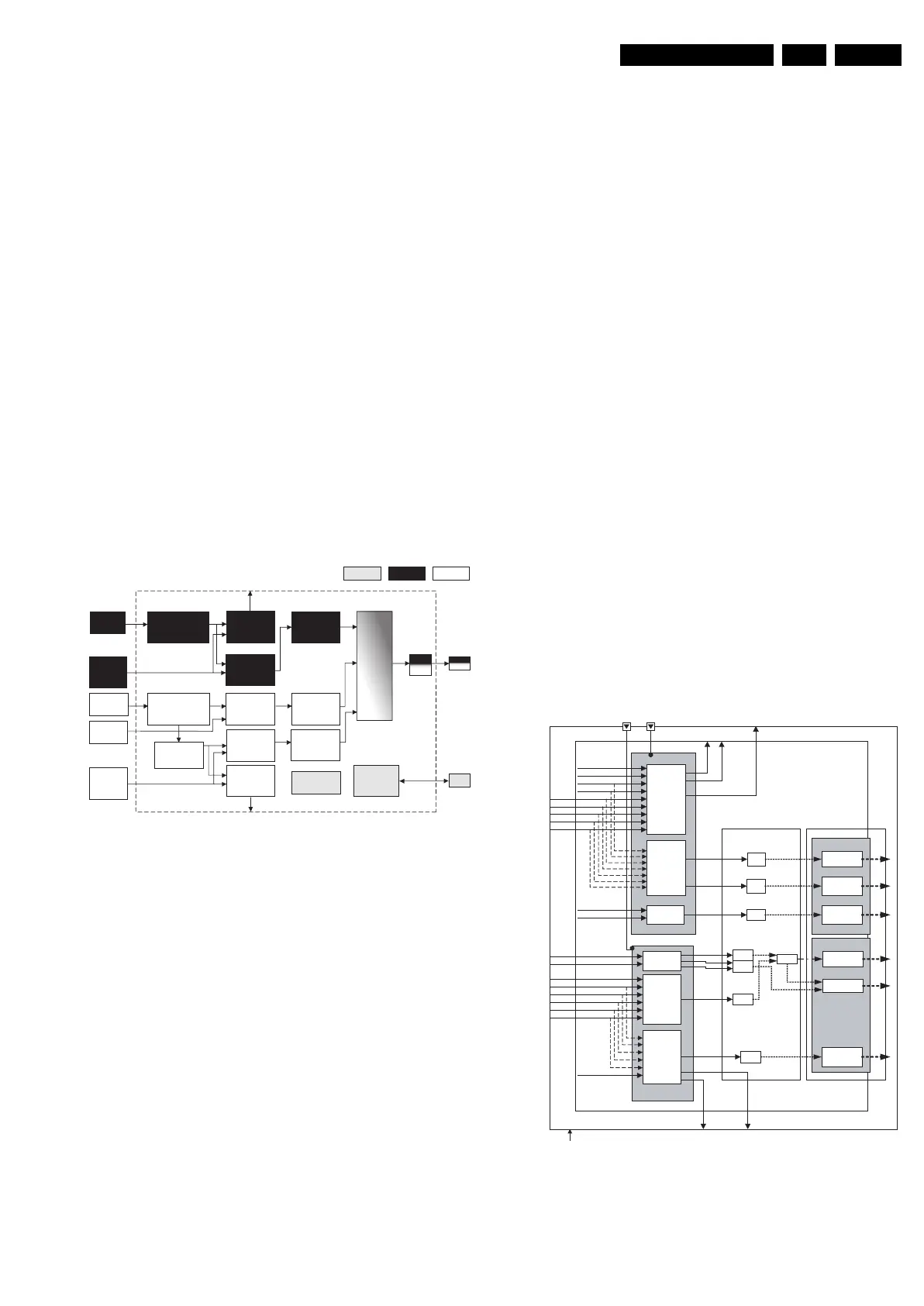
9.5.4 Source Selection
Below the main functions and features of the main blocks in the
MPIF for video and audio are explained.
Figure 9-18 MPIF analog source selection block
Video
IF
Video
IF Processing
Sound IF
Processing
AM
Demod.
Video
output
Selection
CVBS_out
Control Video Sound
Video
ADC
Video
Source
Selection
Sound
2nd IF
Selection
Sound
IF ADC
Audio
Base band
ADC
Clocking
I2C
Interface
Audio
Base band
Selection
Audio
Output
Selection
LR_out
Video
Base
band
Sound
IF
Sound
low-IF
Audio
Base
band
I2D
Link
I2C
Multi-
plexer
F_15710_173.eps
23-09-05
I2D
I2D
Jaguar system
MPIF-
Source Selection
datalinks - video block
datalinks - audio block
switch
CVI1
CVI2
CVBS_IF
CVBS1
YC_COMB
CVBS_DTV
CVBS2
CVBS/YC3
Primary video
Secondary video
SIF
SIF
external
SIF
Primary audio
Secondary audio
DSND2
DSND1
Line out
SCART1 out
SCART2 out / Ext2 out
CVBS B out
A/D datalink3
A/D datalink1
A/D datalink2
CVI switch
Primary
VIDEO
AUDIO
video
selector
Secondary
video/
outputs
selectors
CVBS/YC4
datalink3
datalink1
datalink2
A/D
Y
U
A/D
A/D
Switch
A/D
V
Primary/
Secondary
audio
selector
Audio
outputs
selectors
L5+R5
L4+R4
L3+R3
L2+R2
L1+R1
AM int
AM ext
Y
UV
CVBS A out
cntv cnta
AD
conversion
I2D
transmission
SetVideoConnection()
SetAudioConnection()
E_14700_068.eps
021104