Mechanical Instructions
EN 15JL2.1E AA 4.
Figure 4-24 Backlight cable removal (left side)
Figure 4-25 Chassis after PWB frame removal
Figure 4-26 Bare LCD panel (37”) after plastic frame removal
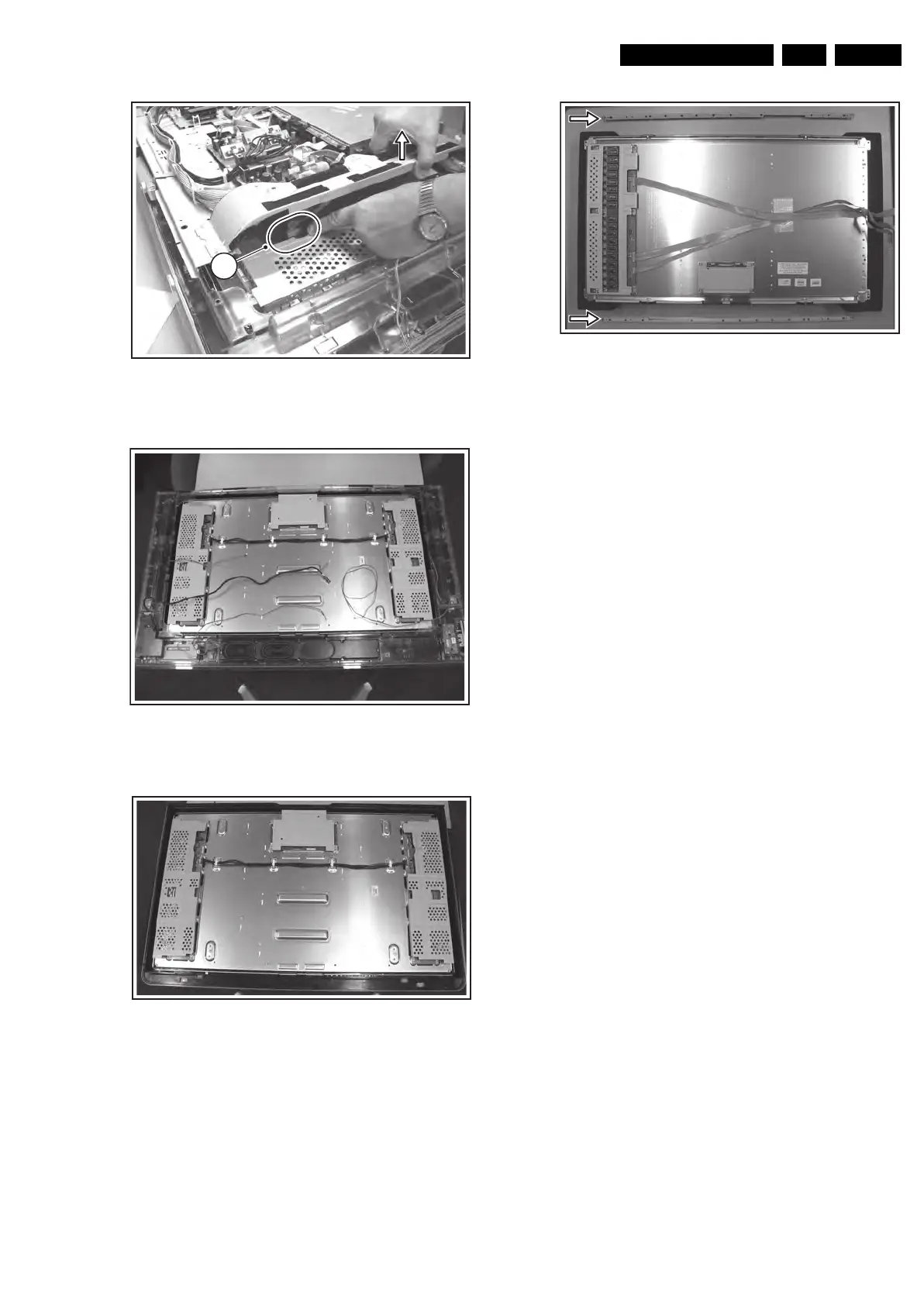
Figure 4-27 Metal fixation bars 32” model
1. Important: Unplug the cables [1] + [2] at the LCD display
(cable [2] is only present in 32” models). Be careful, as the
LVDS connector [1] is very fragile!
2. Remove the Top Control ass’y [3]. No need to unplug.
3. Unplug the following cables and remove them
completely from their cable fixations:
– Card reader cable (USB with supply) at SSB [4a].
– Speaker cables (L, R, and woofer) at SA panel [4b].
– Flat cable on Side I/O panel [4c].
– Flat cable on LED panel [4d].
4. Remove all T10 screws [5] from the mounting frame.
5. Remove all T20 mounting LCD panel screws [6].
6. Lift the metal frame (together with all PWBs) from the LCD
panel. During lift, free the backlight cables [7].
7. After removal of the metal frame, you can lift the plastic
frame from the set.
8. Now, the bare LCD panel is accessible.
Important: On the 32” LCD display two metal fixation bars
are mounted at the top and bottom side (see figure “Metal
fixation bars 32” model“). These must be removed before
sending the display to Service if the display is defective.
4.5 Set Re-assembly
To re-assemble the whole set, execute all processes in reverse
order.
Note: While re-assembling the TV, make sure that:
• All cables are placed and connected in their original
position (see figure “Chassis cable dressing” in the
beginning of this chapter and/or the “Wiring Diagram” in
chapter 6).
• LVDS connector (SSB) is secured with plastic clamp.
• The "grounding" wire between metal shielding of the LED
panel and the TV frame is connected.
F_15710_138.eps
220905
7
F_15710_136.eps
220905
F_15710_162.eps
220905
F_15710_137.eps
220905