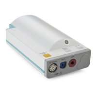
Electrocardiogram/Respiration (ECG/Resp) Measurement
Introduction to the Instrument
25
Safety
To ensure the safety of the patient, the patient-applied parts are isolated from ground by
optical isolators and a transformer. The circuit is also encapsulated in plastic.
Block Diagram of the ECG/Resp
Theory of Operation
As ECG and Resp signals pass from the patient to the Monitor, they progress through stages
corresponding to the logical sections of the circuit, as shown in the block diagram. Circuit-
related faults can generally be isolated to one of the stages.
Transducer
Signals are received through patient electrodes and lead cables via the input connector.
Input Protection Network
The Input Protection Network and ESU filter eliminate extraneous signals. This protects the
rest of the circuitry from defibrillator voltages, high frequency interference signals, and
electrostatic discharges.
ECG ASIC
The signals are processed by the ECG Application-Specific Integrated Circuit (ECG ASIC)
which has an input amplifier with a fixed gain for each of the four electrodes. They are then
passed to a digital-to-analog converter (D/A Converter) for offset compensation and then to
an analog-to-digital converter (A/D Converter). The input/output logic (which is controlled
Input
Protection
Network
ECG
CPU
ROM/RAM
C
RA
LA
LL
RL
Bridge &
Amplifier
Demodulator
ECG
Electrodes
Respiration
To/From
System CP
Excitation
Current
Source
From
Patient
ASIC