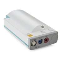
Functional Description of the M3015A Measurement Server Extension Hardware
Introduction to the Instrument
47
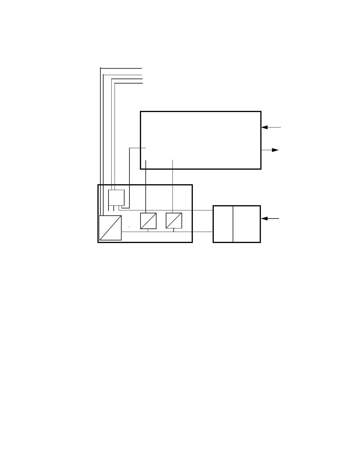
Hardware Block Diagram
Main Functional Areas
• Microstream CO
2
Board - consisting of an 80C552 Controller, the memory system (Flash
ROM, RAM, PLA, etc.), the Flow system (FilterLine recognition system, Inlet, solenoid
valve), Measurement Cell (Exciter, IR Source, Detectors and Temp Sensor) and an analog
section with ADC.
• DC/DC Converter Board -connecting to the Floating/Non-floating isolation area on the
Front-End Board. Consisting also of a multiplexer for Front-End Link communication to
the Measurement Server.
• PRESS/TEMP Front-End Board - consisting of the PRESS/TEMP Front-End and the
Floating/Non-floating Isolation area, all feeding signals to the DC/DC Board.
Power Supply
PRESS/
TEMP
Microstream CO
2
BOARD
MUX
+5V+15V
36-60V
28Vpp
+/-2%
Isoblock
Optocoupler and
Power transformer
36 - 60 Volt
Power Sync
RxD/TxD
FEL Addresses
Gas Inlet
Gas Outlet
Pressure or
Temperatur
Transducer
SRL Connector
to Measurement Server
}
(MSL connector)