66
goes
negative beyond the threshold
established
by
zener
diode
GR54,
diode GR53 starts
conducting
and
the
excess
is
short-circuited
to
earth.
The non-driven
part of
the input stage (TS62) is decoupled for high frequencies,
by means
of
capacitor C59.
This part of
the input
stage
receives the
d.c.
balance voltage and the drift-feedback
voltage from the drift-feed-
back
amplifier.
3.1.
1.5.
Pre-amplifier
The
pre-amplifier
comprises two
amplifier stages, one with
series feedback (TS53
&
TS63)
and
one with
shunt
feedback
(TS54).
The
overall
gain
of
the
pre-amplifier
is
chiefly
determined by the
ratio of
the
shunt-
feed
back
resistance (R97
&
R99) and
series-feedback
resistance (resistance
between
the emitters
of transistors
TS53
and
TS63).
The latter resistance,
and
thus the
overall
gain
of
the
pre-amplifier,
can be varied by
connecting
resistors in parallel to
resistor
R62.
These
parallel resistors
are
selected,
together with a section
of the
input
attenuator, by
means of AMPL.
switch SKI 7.
In
this
way
twelve
different deflection
coefficients
are obtained
(see also
section
3. 1.1.
3.).
Potentiometers
R64 and R99 are pre-set
controls
for the gain of the
pre-amplifier
at
different
settings of
AMPL switch SK17.
3. 1 . 1
.6.
Trigger
pick-off
stage
Transistor TS64
serves
a
twofold
purpose.
It
acts as
an
amplifier stage
for
the
channel
triggering
signal
further
discussed
in section
3.
1.3.1.),
and
as an
emitter-follower
for the signal to be tested.
The test
signal is applied to
the output
amplifier via
AMPL.
potentiometer R4 in the
emitter circuit
of
transistor TS64.
This potentiometer
provides
an uncalibrated,
continuous control of the deflection coefficients.
.
3.1.
1.7.
Drift-reduction circuit
In the event
of no drift phenomena
in the pre-amplifier, attenuator R102,
R40...R44 provides
at
junction
R128-C67 a
voltage which is
exactly
equal to, but
in anti-phase with, the voltage at the gate of
field-effect
transistor
TS51
(junction
R52-R54). This is
true
because
attenuator
R102, R40...R44 is switched over together
with the
gain switch of
the pre-amplifier.
Junction
R128-R52 will
then
be on
earth level (virtual earth point).
When there is
a
drift phenomenon,
junction
R128-R52 carries
half
the
drift
voltage. This voltage is amplified
by
control
amplifier
(TS71
and
TS72)
and, in the correct phase, applied to
field-effect transistor
TS62. The
resulting
feedback
brings
the output
level of
the
amplifier
back to 0 V. The d.c. level of the
feedback
is
adjusted
with DC BAL.
potentiometer
R6.
In order
to
prevent the
base
currents
of
transistors
TS71
and
TS72
from flowing through high-ohmic
resistors
R128
and
R52, they
are
compensated
for
by
means of potentiometer
R126 and resistors R127
and
R129.
Resistor
R131 equalizes the base
impedances of
transistors
TS71
and TS72.
Capacitor
C59
limits
the
feedback at
approximately 100
Hz.
Therefore,
a
variation
of
the value
of potentiometers
R64
&
R99 causes
a
variation
in
the top
of
a
l.f.
square-
wave voltage.
When potentiometers
R64 and R99
are correctly
adjusted, the
pulse
top
is straight.
3.
1.
1.7.
1.
Drift reduction
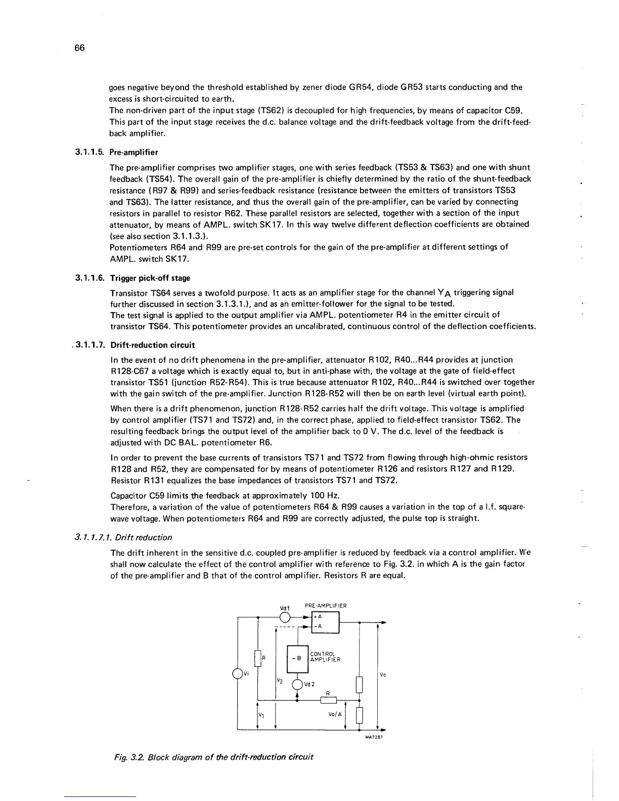
The
drift inherent
in
the
sensitive d.c. coupled
pre-amplifier is reduced
by
feedback via a
control
amplifier.
We
shall
now calculate the effect
of
the
control amplifier with
reference
to
Fig. 3.2. in which A is
the gain
factor
of the
pre-amplifier and
B
that of
the
control amplifier. Resistors R
are equal.
pre-amplifier
Fig.
3.2.
Block diagram of
the
drift-reduction
circuit