73
3.
1.6.4.
Blanking circuit
The
blanking
circuit blanks the c.r.t.
during the
fly-back of
the
time-base
and
unblanks
the c.r.t.
during
the
sweep and
constantly If TIME/cm
switch
SK2
occupies position X via
Y/\.
The
blanking circuit operates on
a
low voltage level and
comprises an
a.c.
and
a
d.c.
path.
Transistor
TS706
is driven
by
the collector signal
of transistor
TS504
in the
sweep-gating multivibrator.
Transistor TS706
forms
together with
transistor TS704 a
single-ended
push-pull circuit.
—
A.C.
Path:
The amplified a.c. components
of
the
blanking signal
are
fed
direct to the
Wehnelt cylinder of
the
c. r.t. via H.T.
capacitor
C707.
—
D.C. Path:
For the d.c. component
of the
blanking signal, the signal
of oscillator
TS702 &
TS703 is
used.
The
oscillator
signal Is modulated with the
blanking signal. The amplified
modulated
signal on the collector
of
transistor TS703 is via capacitor C706
fed
to
demodulator GR702-R713.
After demodulation, also the
d. c.
component of
the
blanking signal is available.
The a.c.
and d.c.
amplifications
are equalized by
means of potentiometer R71 1.
3.1.7.
CALIBRATION
VOLTAGE
The calibration
voltage generator
consists of free-running
multivibrator
TS750 &
TS751.
The
generator
frequency
is approximately 2
kHz.
The
amplitude
of
the
generated square-wave
voltage is
kept
at a
constant
value by
means of zener diode GR751.
The exact
value of the calibration
voltage is set
with
the aid
of
potentiometer
R761.
3.1.8.
POWER
SUPPLY
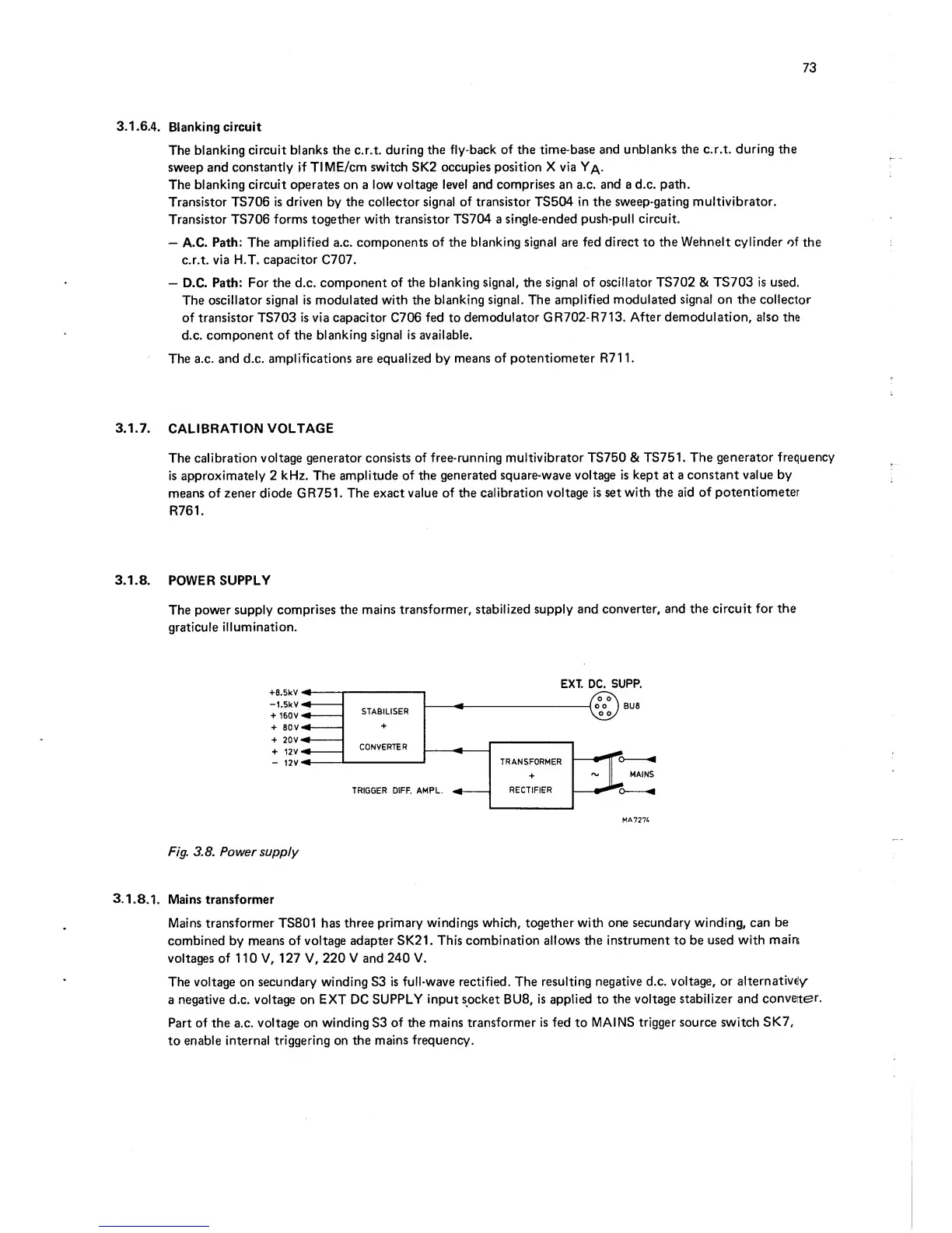
The
power supply
comprises
the mains
transformer,
stabilized supply
and
converter,
and the circuit
for
the
graticule
illumination.
EXT. DC.
SUPP.
Fig.
3.8. Power
supply
3.1.
8.1. Mains transformer
Mains transformer
TS801
has three
primary
windings
which, together with
one secondary winding,
can
be
combined
by
means of voltage
adapter SK21.
This combination
allows the
instrument to
be
used
with
mains
voltages
of
1
1 0
V, 1 27 V, 220 V and
240
V.
The voltage on
secondary winding S3 is
full-wave rectified. The
resulting
negative
d.c.
voltage, or
alternatively^
a
negative
d.c.
voltage on
EXT
DC
SUPPLY input socket BUS,
is applied to
the
voltage
stabilizer and
conveter.
Part
of
the a.c.
voltage on
winding
S3
of the mains
transformer
is
fed
to
MAINS
trigger source
switch
SK7,
to
enable internal
triggering
on
the mains
frequency.