76
3.2.
Checking
and
adjusting
3.2.1.
GENERAL
INFORMATION
All
adjusting
elements
have been
listed in the headings
of
the
various
sections.
The
tolerances mentioned
in the following text apply
to
newly adjusted
instruments
only.
The values
may
differ from those given in
chapter 1.2. CHARACTERISTICS.
3.2.2.
POWER SUPPLY
3.2.
2.1.
Mains current
—
Check that the mains voltage
adapter
(SK21)
has been set
to
220 V and
connect
the Instrument
to
such
a
voltage
(frequency
50 Hz)
—
Switch
the oscilloscope on and check that
the pilot lamp
lights
up
—
Check that
the current consumption does not exceed 200
mA
(measured
with
a
moving-iron meter)
3.
2.
2.
2.
Supply
voltages (R823)
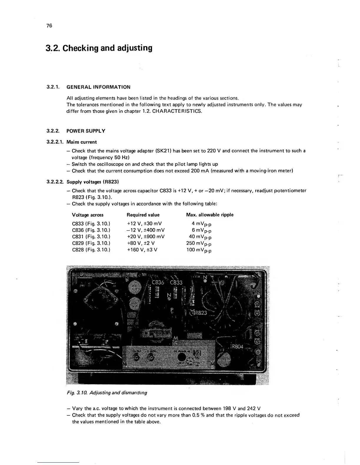
—
Check
that
the voltage across capacitor
C833
is
+12 V,
+
or
—20
mV;
if necessary, readjust
potentiometer
R823
(Fig.
3.10.).
—
Check the
supply voltages in accordance
with
the
following
table:
Voltage
across Required value
Max. allows
C833
(Fig.
3.10.)
+
12 V,
±30
mV 4 mVp.p
C836
(Fig.
3.10.)
-12
V,
±400
mV
6
mV
p-p
C831
(Fig.
3.10.)
+20
V,
±900
mV
40
mVp.p
C829
(Fig.
3.10.)
+80
V,
±2
V 250
mVp.p
C828
(Fig.
3.10.)
+160 V, ±3 V 1 00 mVp_p
Fig. 3. 10.
Adjusting and dismantling
—
Vary
the
a.c.
voltage
to
which
the instrument
is
connected between 198 V
and 242
V
—
Check
that
the
supply
voltages
do not vary
more
than
0.5
%
and
that
the ripple
voltages
do
not
exceed
the values
mentioned
in
the
table
above.