69
Moreover, this transistor improves the stability of the pre-amplifier.
The
external
trigger input
Is
protected against
excessive positive input voltages by means of diodes GR401
and GR402.
3.1.
3.3.
Long-tailed pair circuit (differential amplifier)
The
following description applies
to
internal
triggering.
From the
pre-amplifier
the
triggering signal
is
fed
to
the long-tailed pair
circuit
with
transistors TS403
and
TS404. The
signal
is
applied
to the
base of transistor
TS403
if
+
push-button SK8 Is
depressed and
to
the
base
of
TS404
if
—
push-button
SK9
is depressed.
This allows
triggering
on either the positive or
negative
slope
of
the
signal. The
+
push-button SK8
is
a
mechanical release for
—
button SK9 and is,
therefore, not included
in the circuit diagram.
A d.c.
voltage
which is
variable
with LEVEL potentiometer R3' is
applied
to the base
of
the
non-driven
transistor
of the long- tailed
pair circuit.
As a
long-
tailed
pair
circuit
amplifies the
difference of the base
voltages, the setting
of
potentiometer R3'
determines
which
part of
the
signal will
be
amplified and, thus, the
trigger level.
The output
signal
of
the
long-tailed pair circuit is fed
to
emitter follower TS406. If AUTO
push-button
SK10
is depressed, the
a.c.
component of the emitter
signal of
TS406
is applied to the
full-wave
rectifier with diodes
GR404
and GR406. The
rectified voltage across
LEVEL potentiometer
R3" corresponds to the peak-to-peak
value of the
a.c.
component of the
triggering
signal.
This
d.c. voltage
is
fed
to the base
of
transistor
TS404
of
the
long-
tailed pair circuit. The
result
is that in the auto
mode
the trigger
level
range
corresponds
to the peak-
to-peak
value
of
the
triggering
signal.
3. 1.3.4.
Synchronisation separator
If
T.V.
push-button SKI 3 is depressed,
a
synchronisation
separator
for television
is
inserted
into
the triggering
signal
path.
The sync
separator comprises transistor
TS407.
The television signal is clipped in such
a
way
that
only
the
synchronising
pulses reach the collector
of
transistor
TS407.
In
positions
.2
jus
to
20
jus (TV LINE)
of TIM E/cm switch
SK2,
these
pulses are supplied
direct to emitter
follower
TS408.
In positions
50
jus
to
.5
s
(TV FRAME)
the composite synchronising signal is Integrated
by
means of R439,
C412, GR407, R442 and
C413
at such
a
timexonstant
that the frame
pulses
are
separated. The separated
pulses are applied
to emitter
following
TS408.
3.1.3.5.
Trigger-pulse
shaper
The
trigger-pulse
shaper comprises
transistors TS501
& TS502
in Schmitt-trigger configuration.
With
a
repetitive
trigger
signal,
a square-wave voltage of
constant
amplitude and width arises
at
the
collector
of
TS502.
This
square-wave
voltage is differentiated by C502 and R514 into narrow positive and negative pulses. The
positive
pulses
are
short-circuited by GR501 so that sweep-gating
multivibrator
TS503-TS504 receives
only
negative
pulses.
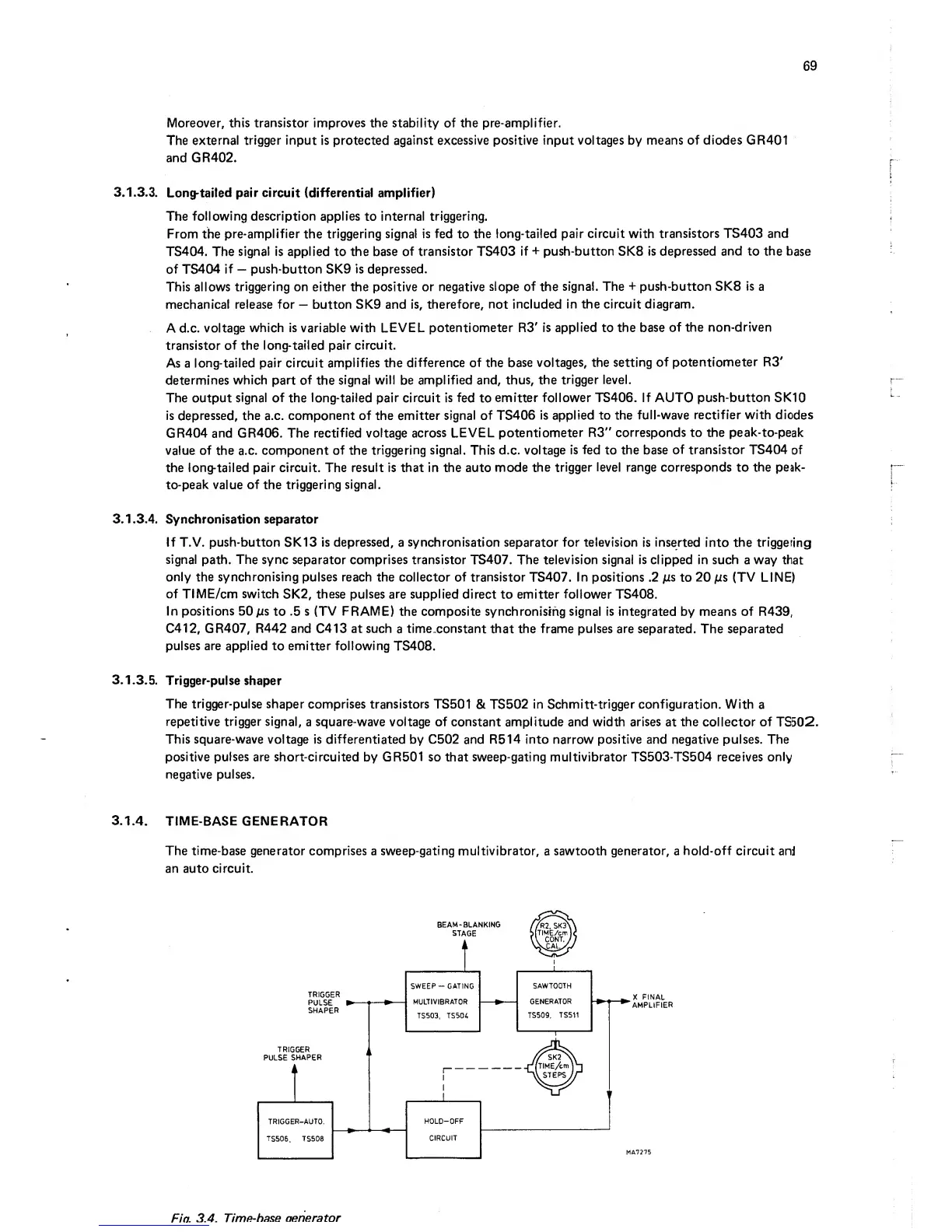
3.1.4.
TIME-BASE
GENERATOR
The
time-base
generator comprises a sweep-gating multivibrator,
a
sawtooth
generator,
a
hold-off circuit
and
an auto
circuit.
X
FINAL
"amplifier
Fio.
3.4.
Timfhhase aenerator