68
3.1.
1.8.
Output
amplifier
From the wiper
of
AMPL. potentiometer R4,
the signal is
applied
to
the base.of transistor
TS66 which
is part
of
a
differential amplifier.
By
varying
the
series
feedback
of
this
amplifier
by
means of
potentiometer R1 1
1,
the
overall
gain
of
the
Y/\
channel can
be set. The
RC
combination R113-C62 corrects
the gain factor
at high
frequencies.
The
Y
shift voltage
derived from POSITION
potentiometer R1 1 is applied
to
the base
of transistor
TS67.
If
BEAM SELECTOR
switch SK14
is
not depressed,
the
voltage on
the
base of
TS67 is such
that the
trace
is shifted
off
the screen
and cannot
be
brought
back with
the POSITION
potentiometer.
From the differential
amplifier the signal is fed
to the final
stage
which consists off
two single-ended
push-pull
sections,
viz. TS57,
58, 59,
68 and
TS69,
73,
74,
76. From these two sections, the signal is
applied
to the Y
deflection
plates.
The circuit
with transistor
TS56 wilt be discussed
together with the c.r.t. circuitry
(section
3. 1.6.
3.).
In
position
X
via
Y/\,
the
signal is fed
to
the X
output amplifier via emitter follower
TS75. In this case
the
channel Y^
output
amplifier
is inoperative.
3.1.2.
CHANNEL
Yb
VERTICAL AMPLIFIER
As this
channel is identical
to channel Y
/\
with exception of
the
circuitry
for
external X
deflection,
the
description of
channel
Y;\
also holds good for
channel
Yg. Components
are assigned
in
the
200-299
range
(corresponding
to
numbers in
the
1-99
range
for
channel Y^)
and
in the
300-399
range (corresponding
to
range
100-199
in channel Y/\).
3.1.3.
TRIGGERING
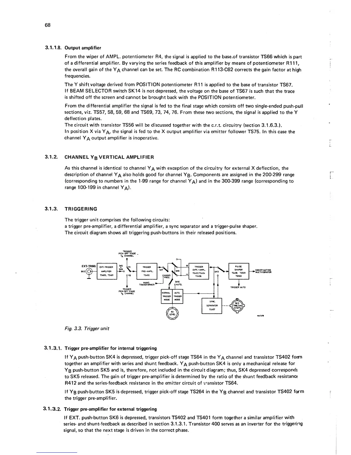
The
trigger unit
comprises
the
following
circuits:
a trigger pre-amplifier,
a
differential amplifier,
a
sync
separator
and a
trigger-pulse shaper.
The circuit
diagram
shows all
triggering
push-buttons in their released positions.
PICK-OFF
STAGE
^
ya
channel
Fig.
3.3.
Trigger unit
3.1
.3.1. Trigger
pre-amplifier for
internal triggering
If
Y/\ push-button SK4 is depressed, trigger
pick-off
stage
TS64
in the Y/\
channel and
transistor
TS402
form
together an
amplifier with
series and shunt feedback.
Y/\
push-button
SK4
is
only a
mechanical
release
for
Yb
push-button
SK5
and is,
therefore,
not
included
in the circuit diagram; thus,
SK4
depressed
corresponds
to SK5
released. The gain
of
trigger
pre-amplifier
is determined by the
ratio of
the shunt
feedback
resistance
R412
and
the series-feedback resistance in the emitter circuit
of
transistor
TS64.
If
Yb
push-button
SK5
Is depressed, trigger
pick-off
stage
TS264
In the
Yg
channel and transistor TS402
form
the trigger
pre-amplifier.
3.1.
3.2.
Trigger
pre-amplifier for external triggering
If
EXT.
push-button SK6
is
depressed,
transistors
TS402
and
TS401 form together
a
similar
amplifier
with
series- and
shunt-
feedback
as
described
in
section
3.
1.3.1. Transistor
400
serves
as an
inverter
for the
triggering
signal,
so
that the next
stage
is driven
in
the
correct phase.