94
3.3.11.
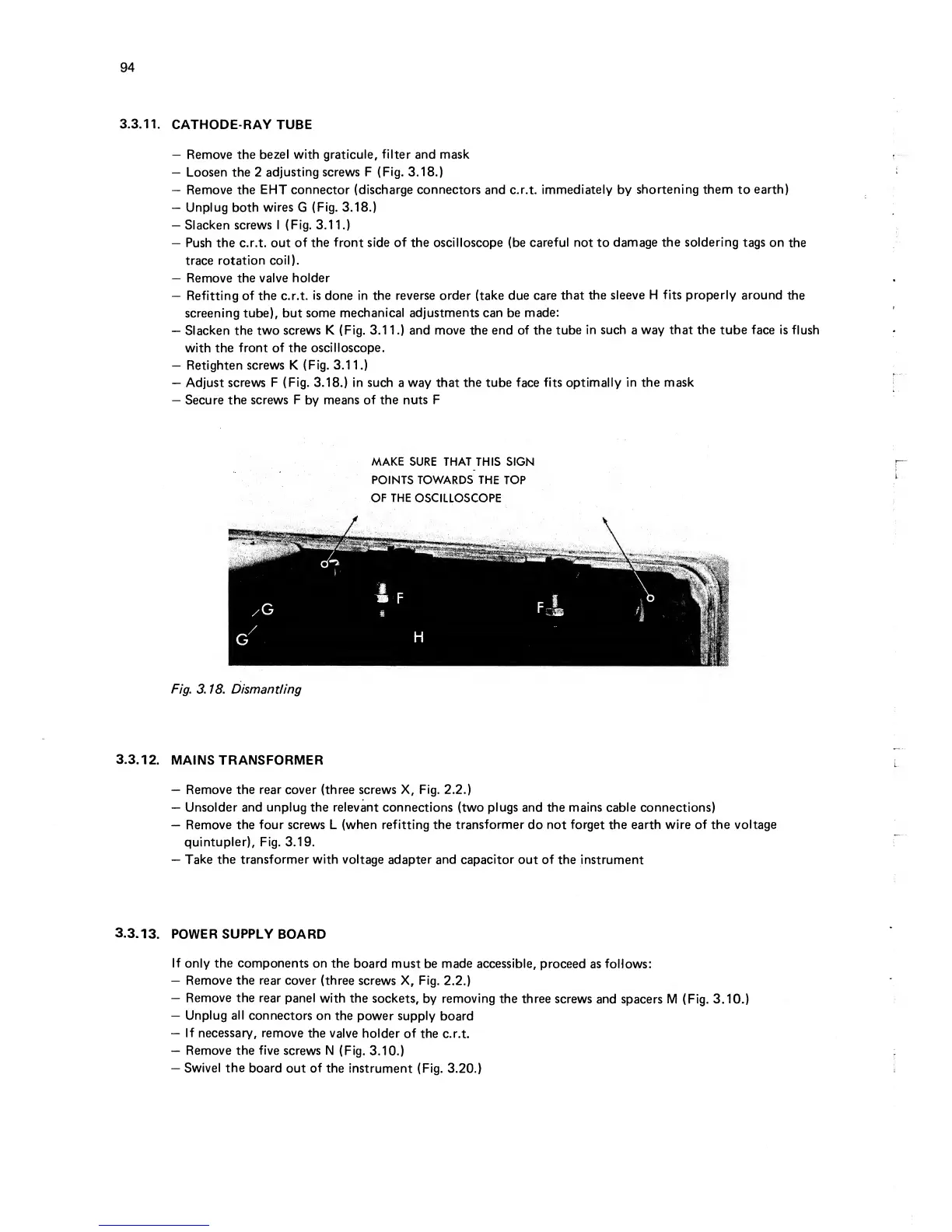
CATHODE-RAY TUBE
—
Remove
the bezel with graticule,
filter and mask
—
Loosen the 2
adjusting screws F
(Fig.
3.18.)
—
Remove the EHT
connector (discharge connectors
and c.r.t.
immediately by
shortening them
to
earth)
—
Unplug
both
wires
G
(Fig.
3.18.)
—
Slacken screws I (Fig.
3.1
1.)
—
Push
the
c.r.t. out
of the front side of the oscilloscope (be
careful not
to
damage
the soldering
tags
on
the
trace rotation
coil).
—
Remove the valve
holder
—
Refitting of the c.r.t.
is done in the reverse order (take due care
that the
sleeve H fits properly around
the
screening tube), but
some
mechanical adjustments can be made:
—
Slacken the two
screws K (Fig.
3.1 1
.)
and move
the
end of the
tube
in such
a
way that the tube face
is flush
with the
front
of the
oscilloscope.
—
Retighten screws K
(Fig.
3.11.)
—
Adjust
screws F (Fig.
3.18.)
in such
a
way that the tube
face
fits optimally
in the mask
—
Secure the screws
F
by
means of the
nuts F
MAKE
SURE THAT
THIS SIGN
POINTS TOWARDS THE
TOP
OF
THE
OSCILLOSCOPE
Fig. 3. 18. Dismantling
3.3.12.
MAINS TRANSFORMER
—
Remove the rear cover (three screws X, Fig.
2.2.)
—
Unsolder and
unplug
the
relevant
connections (two
plugs
and the mains cable connections)
—
Remove the four screws
L
(when refitting the
transformer
do
not forget the earth
wire
of
the voltage
quintupler), Fig.
3.19.
—
Take
the transformer with voltage
adapter and capacitor out of
the instrument
3.3.13.
POWER
SUPPLY
BOARD
If
only
the
components on
the
board must be made accessible,
proceed
as follows:
—
Remove the rear cover
(three screws X, Fig.
2.2.)
—
Remove the rear
panel
with the
sockets,
by
removing
the three
screws
and spacers
M (Fig.
3.10.)
—
Unplug
all
connectors on
the power supply
board
—
If necessary,
remove
the valve
holder
of the
c.r.t.
—
Remove
the
five
screws N
(Fig.
3.10.)
—
Swivel
the
board
out of the
instrument (Fig.
3.20.)