72
3.
1.6.2.
C.r.t.
circuit
By
means
of INTENS
potentiometer RIO
the brightness of the
display
can be
continuously controlled.
The
maximum
beam
current is set
by potentiometer
R801.
The
control
range
of
the
INTENS potentiometer
can be
preset
by
means
of
potentiometer R802.
A
brightness modulation
facility,
a.c.
coupled,
is provided on Z MOD input
socket BU7.
The
display
can be
focused
by
means of FOCUS
potentiometer
R9. In
a
split-beam
c.r.t. as
used
in this
oscilloscope,
focusing has certain
consequences.
These
consequences
and
their
remedies
are
discussed in
section 3. 1.6. 3.
Astigmatism is corrected
on
a
low-impedance level by
means of
potentiometer R809
via
emitter
follower
TS801.
With
the
aid of potentiometer R812
barrel and pin-cushion distortion
is
corrected.
Potentiometer R813 provides trace
rotation
control and allows the
time-base line
to
be
accurately
aligned with
the horizontal graticule lines.
3.
1.6.3.
Focusing in the split-beam c.r.t.
In the split-beam c.r.t. the electron beam is split into
two
parts which
form
the
traces of
the
Y
and
Yg
channel.
Both
traces
are controlled
independently
by
the
controls of
both
channels. The electron beam is
focused, however, before It is split and,
therefore,
there is
only one focus control. This
mono-knob
control
of
the focus has the
following
consequence.
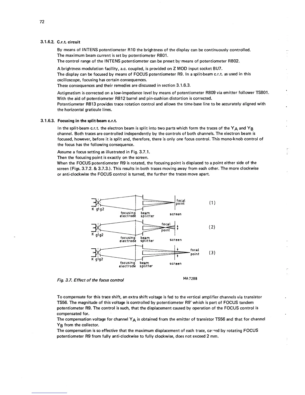
Assume a focus setting as illustrated in Fig. 3.7.1.
Then
the
focusing
point
is
exactly on
the screen.
When
the FOCUS
potentiometer
R9 is rotated, the
focusing point
is displaced to a
point
either side
of
the
screen (Figs. 3.7.2. & 3.7.3.).
This
results in both traces
moving
away
from each other. The
more
clockwise
or
anti-clockwise the
FOCUS
control
is turned, the
further the traces
move
apart.
(
1
)
(
2
)
(3)
Fig. 3.7. Effect of the focus control
MA7288
To
compensate
for
this trace shift, an extra shift
voltage is fed
to the
vertical amplifier
channels via
transistor
TS56.
The
magnitude
of
this voltage
is
controlled
by
potentiometer
R9' which is part
of
FOCUS
tandem
potentiometer
R9. The
control
is
such, that
the displacement
caused
by
operation
of
the FOCUS
control
is
compensated for.
The compensation
voltage
for channel
is obtained from
the emitter
of transistor TS56 and that
for
channel
Yb
from
the
collector.
The compensation is
so
effective
that the maximum displacement
of
each trace, cav'^^ed by
rotating
FOCUS
potentiometer
R9
from
fully anti-clockwise
to
fully clockwise, does not exceed 2 mm.