Mechanical Instructions
EN 19Q552.2E LA 4.
2011-Jun-01
back to
div. table
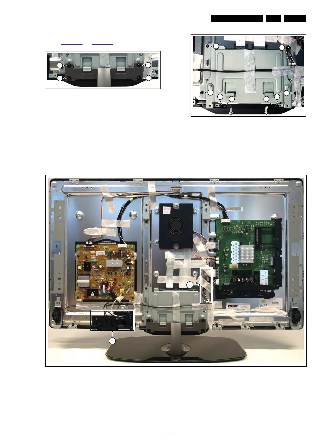
4.3.6 Keyboard Control, IR & LED Board
Refer to Figure 4-19
and Figure 4-20 for details.
Figure 4-11 Keyboard control, IR & LED board [1/2]
Figure 4-12 Keyboard control, IR & LED board [2/2]
1. Remove the stand [1].
2. Remove the stand subframe [2].
3. Remove the screws [3], unplug the connector and take the
board out.
When defective, replace the whole unit.
Figure 4-13 LCD panel [1/3]
1. Remove the SSB as described earlier.
2. Remove the PSU as described earlier.
3. Remove the tweeters with their subframes and subwoofer
as described earlier.
4. Remove the stand and -subframe as described earlier.
5. Remove the cables [1].
6. Remove the mains switch subframe [2].
7. Remove the keyboard control-, and IR & LED board as
described earlier.
8. Remove all remaining cables and subframes.
9. Use a screwdriver to release the catches [3] that secure the
panel.
19101_009_110407.eps
110407
1
1
1
1
19101_006_110407.eps
110407
2
2
2 2
2
2
3 3
19101_005_110407.eps
110407
2
1