Circuit Descriptions
EN 53Q552.2E LA 7.
2011-Jun-01
back to
div. table
7.2 Power Supply
7.2.1 Power Supply Unit Blockbuster sets
Where detailed information for power supply boards is given in
this manual, the boards should be repaired where possible.
In this manual, detailed board schematics are given for Delta
power supply units (refer to schematics 10-1
, 10-2 and 10-3),
where for FSP- and LGIT power supply units the functional
block diagrams are given (refer to Figure 7-3
, Figure 7-4 and
Figure 7-5
).
In future releases of the manual, more schematics will be
published.
7.2.2 Connector overview Blockbuster (series xxPFL6600/xx)
Table 7-1 Connector overview 32" sets
Table 7-2 Connector overview 37" sets
Table 7-3 Connector overview 40" sets
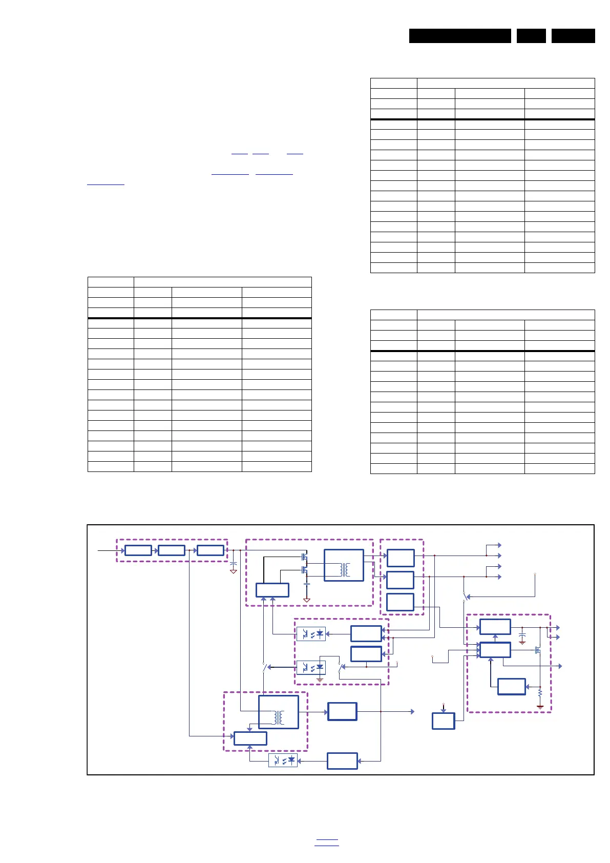
7.2.3 Functional block diagram FSP Supply Units FPS096-4FS01(REV01) & FSP110-4FS01B
Figure 7-3 Functional block diagram FSP supply units FPS096-4FS01(REV01) & FSP110-4FS01B
Connector
no. 1308 1316 1M95
Descr. Mains to display to SSB
Pin CN1 CN2 CN4
1 N A2 +3V3SB
2 L n.c. Standby
3 - pin 5 GND1
4 - n.c. GND1
5 - pin 3 +12V3
6 - n.c. +12V3
7-OCD +Vsnd
8 - n.c. GND1
9 - A1 BL-ON-OFF
10 - n.c. BL-DIM1
11 - pin 13 BL-I-CTRL
12 - n.c. POK
13 - pin 11 +24V
14 - n.c. GND1
15 - GND1 -
Connector
no. 1308 1316 1M95
Descr. Mains to display to SSB
Pin CN1 CN2 CN4
1 N Anode_R +3V3stdby
2 L n.c. Standby
3 - R5 Cathode GND1
4 - R4 Cathode GND1
5 - R3 Cathode +12V
6 - R2 Cathode +12V
7 - R1 Cathode +Vsnd (+24V)
8 - L1 Cathode GND_SND
9 - L2 Cathode BL-ON-OFF
10 - L3 Cathode BL-DIM1 (Vsync)
11 - L4 Cathode BL-I-CTRL
12 - L5 Cathode POK
13 - n.c. +24V (AL2_DVBS)
14 - Anode_L GND1
15 - - -
Connector
no. 1308 1316 1M95
Descr. Mains to display to SSB
Pin CN1 CN2 CN4
1 N Anode 1+ +3V3stdby
2 L n.c. Standby
3 - Cathode 1- GND1
4-n.c. GND1
5 - Anode 2+ +12V
6-n.c. +12V
7 - Cathode 2- +Vsnd (+24V)
8 - n.c. GND_SND
9 - Anode 3+ BL-ON-OFF
10 - n.c. BL-DIM1 (Vsync)
11 - Cathode 3- BL-I-CTRL
12 - n.c. POK
19103_002_110531.eps
110601
MAINS
RECTIFIER
EMI
FILTER
FUSE
+
Mains CAP.
PWM DRIVER
SWITCH
CIRCUIT
PWM DRIVER
CIRCUIT
AC INPUT
TRANSFORMER
POWER
TRANSFORMER
POWER
RECTIFIER
FILTER
&
RECTIFIER
FILTER
&
RECTIFIER
FILTER
&
LED DRIVER
24V
Vsnd
12Vssb
Val
BOOST
CONVERTER
CONSTANT
CIRCUIT
CURRENT
+
CAP.
AL_LED Output
CONSTANT
CIRCUIT
VOLTAGE
OVP DETECT
RECTIFIER
FILTER
&
3V3stdby
AR_LED Output
Backlight
Current
Controller
BL_I_CTL
BL_ON_OFF
STB
BL_ON
LED Controller × 2
Mains Converter
POK
CONSTANT
CIRCUIT
VOLTAGE
STB ON
STB ON
AUX POWER
Standby Power Converter
Brown In/Out sense
Mains Filter and Rectifier
Output Rectifier and filter
Feedback Circuit
BL_DIM