onlinecomponents.com
Description of the Inline Controller
7805_en_02 PHOENIX CONTACT 2-15
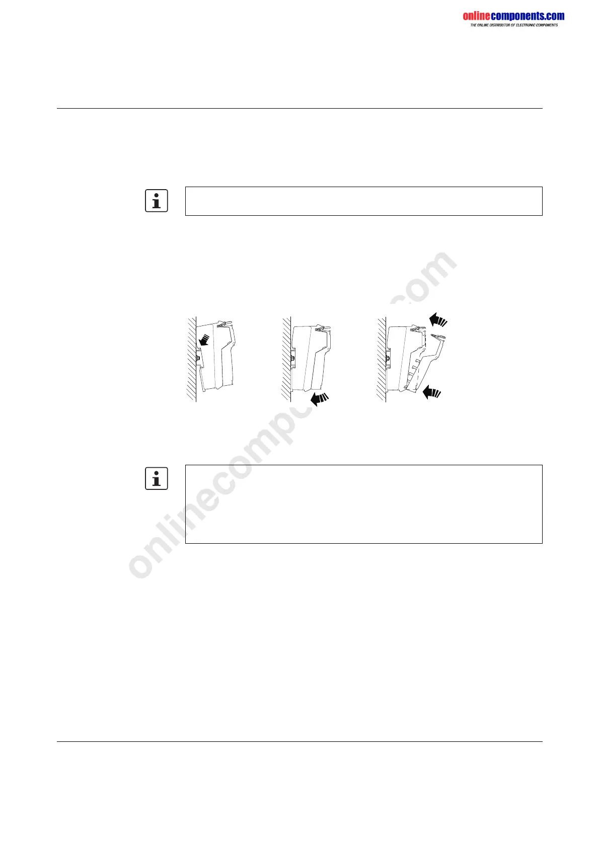
Mounting When mounting the Inline Controller, proceed as shown in Figure 2-11:
• Disconnect the power to the station.
• Place the Inline Controller onto the DIN rail from above (detail A) and push down (detail B).
• Then attach all the electronics bases required to set up the station. Observe the
information provided in the above user manuals.
• Once all the bases have been snapped on, plug the connectors into the appropriate
bases.
First, place the front connector shaft latching in the front snap-on mechanism
(detail C1).
Then press the top of the connector towards the base until it snaps into the back
snap-on mechanism (detail C2).
Figure 2-11 Snapping on the Inline Controller
Removal When removing the Inline Controller, proceed as shown in Figure 2-13 on page 2-16:
• Disconnect the power to the station.
Ensure that all featherkeys and keyways on adjacent terminals are securely interlocked.
BA
C1
C2
C
74060007
Unlike other Inline terminals, the Inline Controller is removed by tilting it away from the DIN
rail. This requires the Inline terminal to the right to be removed prior to removing the Inline
Controller. The right connector of the Inline Controller must also be removed.
Remove the third and fourth connectors to access the right base latch.
It is therefore recommended that all connectors be removed prior to removing the Inline
Controller.
 Loading...


