onlinecomponents.com
UM EN ILC 1XX
3-4
PHOENIX CONTACT 7805_en_02
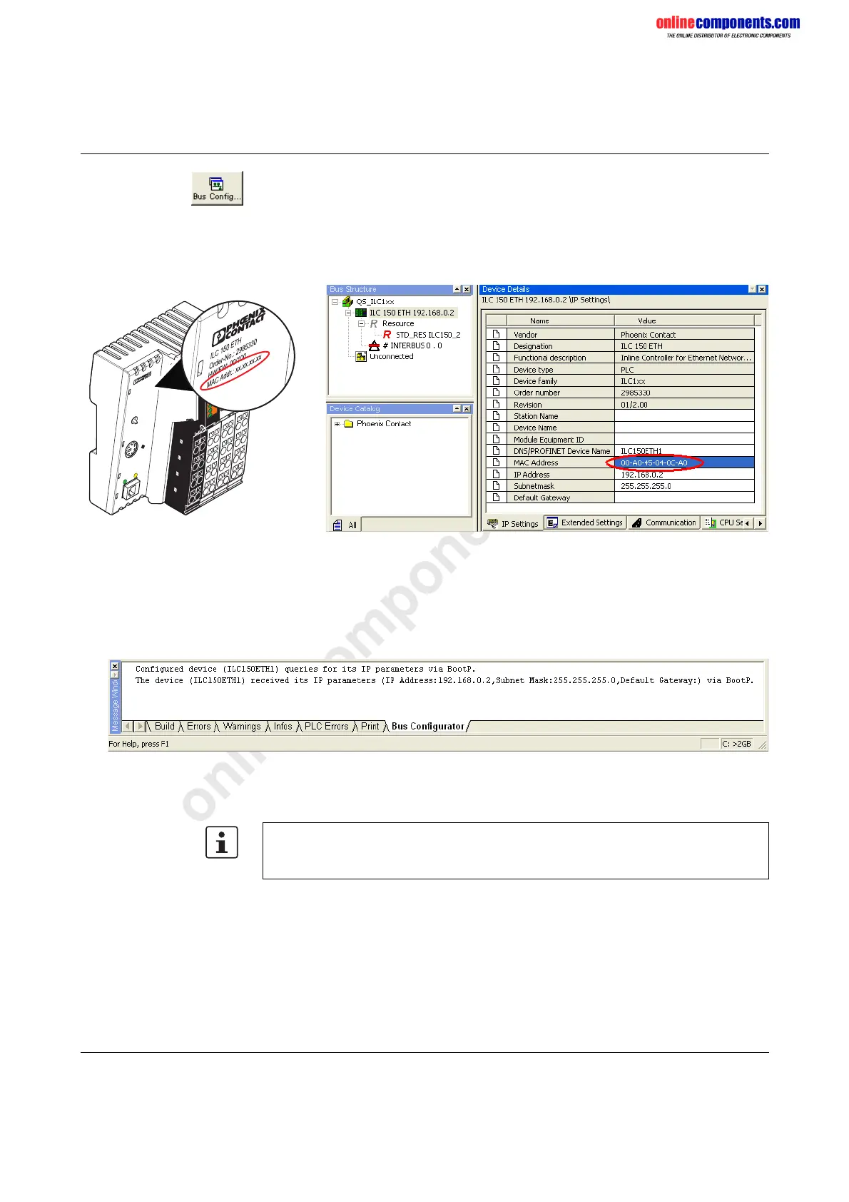
• Switch to the bus configuration workspace.
• Select the controller node (here: "ILC 150 ETH").
• Select the "IP Settings" tab in the "Device Details" window.
• Enter the MAC address of the controller (see Figure 3-3 on page 3-4). This is printed
on the device and starts with "00.A0.45".
Figure 3-3 Entering the MAC address
• Perform a cold restart for the controller. To do this, switch the supply voltage off and
then on again after about 2 seconds.
The controller is assigned the IP address, which is specified in the project for the controller.
The following message appears in the message window in the "Bus Configurator" tab.
Figure 3-4 Message window following BootP
The IP address is now permanently stored on the controller Flash memory.
ILC 150 ETH
Order-No.: 2985330
HW/FW: 00/100
MAC Addr.: xx.xx.xx.xx
UL
US
UM
I1
I3
I2
I4
I6
I5
I8I7
R
E
S
E
T
E
Q
2
Q
1
Q
3
Q
4
1
P
R
G
FF
LNK
ACT
M
R
E
S
E
T
R
U
N
/P
R
O
G
S
T
O
P
FR
PF
RDY
FAIL
7805A012
For additional information about setting the IP address with PC WorX/PC WorX Express,
please refer to the Quick Start Guides for the software used, the ILC 150 starter kit, and
the ILC 150 construction kit.
 Loading...


