© PSI (Photon Systems Instruments), spol. s r. o.
22
3.6 CONNECTION SCHEMA
Depending on the use of optional modules and the set-up of the PBR FMT150, the connection schema for the optional and
standard modules with the PBR FMT150 control unit rear panel may differ. Please refer to Tab. 5 below to see the possible
order of connecting the different modules to the PBR FMT rear panel.
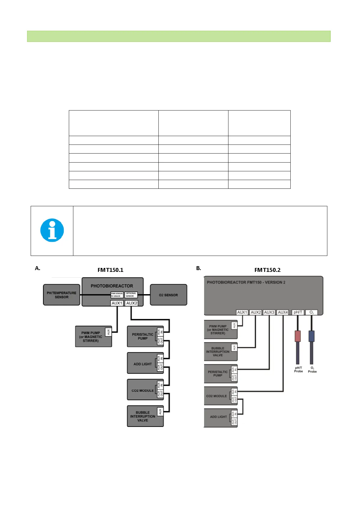
Devices for which the interconnection is possible can be connected together in a series by AUX IN and AUX OUT connectors
according to the recommended order. Please refer to Fig. 10 for recommended schematic connection setup for all available
modules and accessories.
DEVICE
INTERCONNECTION
POSSIBLE
Bubble Interruption Valve
Tab. 5 External connectors.
Important: Please note that Bubble Interruption Valve must be always connected to the AUX2
connector and Magnetic stirrer and PWM pump always to connector AUX1. In case of magnetic stirrer
and PWM Pump, only one of the two devices can be connected to the PBR FMT150 at one time.
Please note that the AUX3 and AUX4 connectors are available only in the FMT150.2.
Fig. 10 Schematic of recommended set-up for interconnecting available modules with PBR FMT150 control unit. A) Scheme valid for
FMT150.1 version. B) Scheme valid for FMT150.2 version.