© PSI (Photon Systems Instruments), spol. s r. o.
20
3.5 REAR PANEL FOR VERSION FMT150.2
The rear panel houses connectors for all connecting cables (Fig. 9). Please note that the numbers in the next section
correspond to the numbers in Fig. 9.
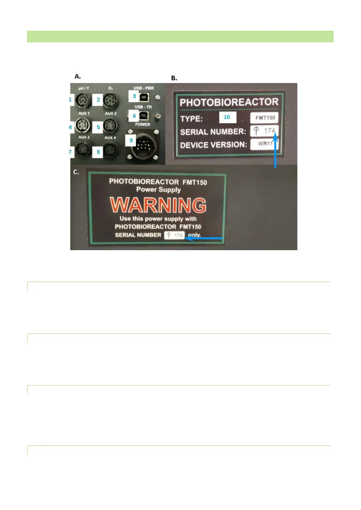
Fig. 9 Photobioreactor control unit and its power supply rear panel. A) Back panel of the Photobioreactor control unit. B) Serial number
on the front panel of the PBR FMT150 unit. C) Rear panel of the power supply with the serial number (blue arrow).
3.5.1 CONNECTOR FOR PH/TEMPERATURE SENSOR
pH/temperature sensor should be plugged to this connector when in use. PBR FMT150 control unit recognizes when the
sensor is connected and will automatically control the operation of the sensor.
3.5.2 CONNECTOR FOR O
2
SENSOR
O
2
sensor should be plugged to this connector when in use. PBR FMT150 control unit recognizes when the sensor is
connected and will automatically control the operation of the sensor.
3.5.3 USB PBR COMMUNICATION CONNECTOR
USB communication cable is provided as part of the PBR FMT150 package when purchased with the Remote Control System
to connect the PBR FMT150 with the computer. This connection has to be made for the communication of the PBR FMT150
via the PBR software.
3.5.4 AUX1 CONNECTOR
AUX1 connector should be used for the CO
2
sensor, peristaltic pump, PWM pump, additional light or magnetic stirrer
(please see Fig. 10 on page 22 for detail description of possible connection schemes).