© PSI (Photon Systems Instruments), spol. s r. o.
48
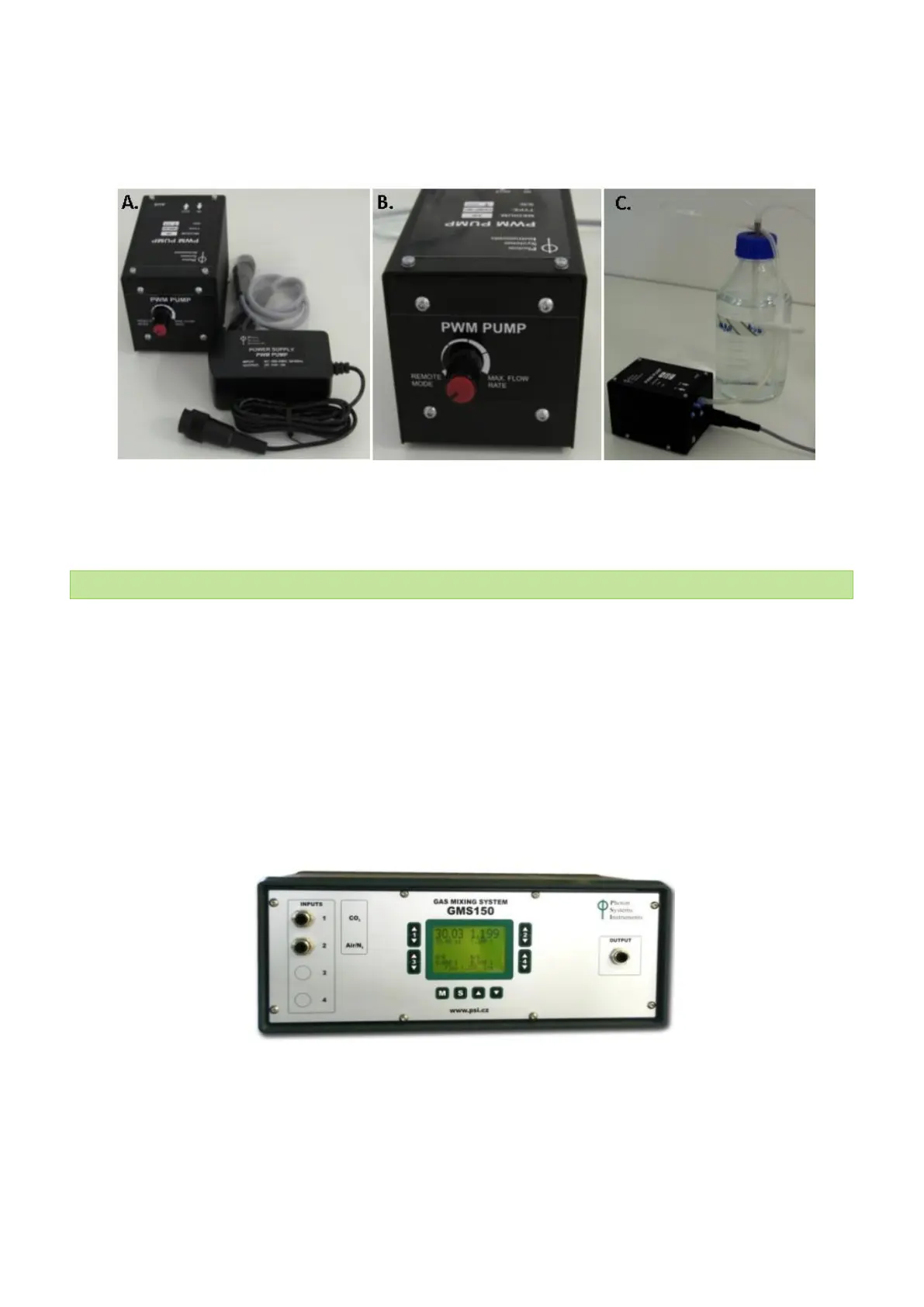
• Connect the short silicone tube to the IN port on the rear panel of the PWM Pump. (Note: This improves supply
of homogeneous gas flow to the pump). Connect the silicone tubing between the OUT port on the PWM Pump
rear panel with the humidifier bottle (Fig. 37C) or with the bubble interruption valve (Fig. 19) depending on the
configuration used.
Fig. 37 PWM Pump. A) PWM Pump components. B) Front panel with the speed control knob in REMOTE MODE position. C) Connection
of the PWM Pump with the humidifier bottle.
5.8 GAS MIXING SYSTEM GMS 150
Gas Mixing System GMS 150 (Fig. 38) can produce precise mixtures of up to 4 different gases. The flows of the individual
input gases are measured by thermal mass flow meters and adjusted by integrated mass flow controllers. The gas mixture
is thoroughly homogenized, before leaving the device. The input and output gas connectors are of Prestolok type allowing
fast and secure connection to a variety of tubes.
The gas mixer can have up to four channels (gases). The standard version of the system includes two channels:
• Channel 1 supplies Air-N
2
mixture or Air and has flow rate 40 – 2,000 ml/min
• Channel 2 supplies CO
2
and has flow rate in range 0.8 – 40 ml/min
Please note that when one GMS is used to supply gas to more than one photobioreactor, the use of one PWM pump per
photobioreactor is required to supply portion of the gas from the gas mixing system to the bioreactor without affecting
the gas flow among the bioreactors.
Fig. 38 GMS 150.
The GMS 150 mass flow meters and controllers can operate gas flows ranging from ml/min to tens of l/min. Typically, the
controllers of GMS 150 operate in the lowest range 0 – 8 ml/min and in the highest range 0 – 2,500 ml/min.
The user can define the required gas mixture either by setting the flows of the individual gases (e.g., 980 ml/min of N
2
and
20 ml/min of CO
2
) or by setting the required relative composition of the gas mixture (2% CO
2
) and the mixture gas flow