© PSI (Photon Systems Instruments), spol. s r. o.
31
4.4 GAS SUPPLY
The gas supply to the photobioreactor consists of four main parts – pressurized gas source, bubble humidifier, the bubble
interruption control valve, and gas dispenser tube (Fig. 19). All parts are connected with flexible silicone tubing.
The following instructions describe the proper installation of the gas supply for the photobioreactor:
• Connect gas source (Note: this can be pressurized gas from air pump or pressurized mixed air from other sources)
with the bubble interruption valve via the silicone tubing.
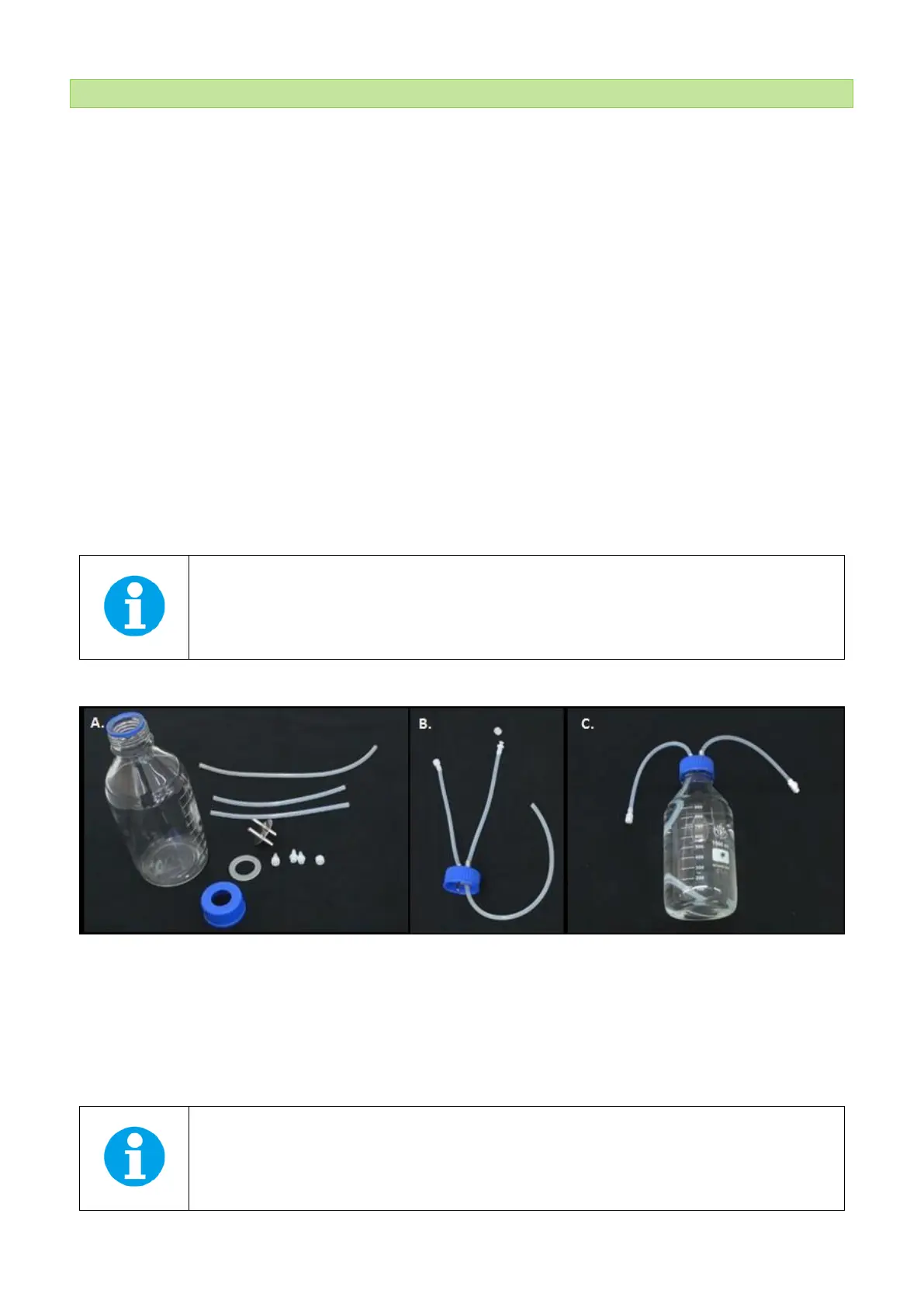
• Prepare the bubble humidifier bottle: Components needed for bottle assembly are shown in Fig. 18A. Connect
silicon tubing to the metal portion of the lid with the ports and insert into the screw cap. One end of the silicon
tubing has FTLL Luer Lock (n°3 in Tab. 4) and Lock Ring Plug (n°4 in Tab. 4), the second has MTLL Luer Lock (n°1 in
Tab. 4), as shown in Fig. 18B. Other silicon tubing of about 15-20 cm is connected to the other side of the metal
sleeve (Fig. 18B). Fill the bottle up to 1 liter with distilled water, insert the sealing ring into the screw cap and close
loosely the bottle with the assembled lid and cover by aluminium foil. The ends of all the tubings should be
covered with aluminium foil and the assembled aeration bottle should be autoclaved (Fig. 18C).
• After autoclaving, connect the bubble humidifier bottle as described in the following steps. Remove the Lock ring
plug from the silicon tubing and connect the MTLL Luer Lock with FTLL Luer Lock placed in the main gas dispenser
tubing. Prepare silicon tubing of approximately 30 – 35 cm length and connect it with bubble interruption valve
as shown in Fig. 19. Connect 20 µm air filter* with the MTLL Luer Lock end of the silicon tubing from the humidifier
bottle and via other FTLL Luer Lock connect with the silicon tubing coming from the bubble interruption valve.
Fig. 18 Assembly of the bubble humidifier bottle. A) Components needed for the assembly of the bottle. B) Assembled lid. C) Assembled
bubble humidifier bottle.
• Connect the bubble interruption valve cable with the AUX2 connector on the back of the FMT150 or with the
peristaltic pump via the AUX Out (see Fig. 10 on page 22).
• Switch on the air pump or other pressurized gas source.