© PSI (Photon Systems Instruments), spol. s r. o.
9
The array of high-power light emitting diodes (LEDs) is located behind the cultivation vessel.
In the bottom corner of the front of the vessel is a semiconductor light sensor for measuring fluorescence emission and
suspension optical density by attenuation of light that was emitted from the LEDs (Fig. 1E)
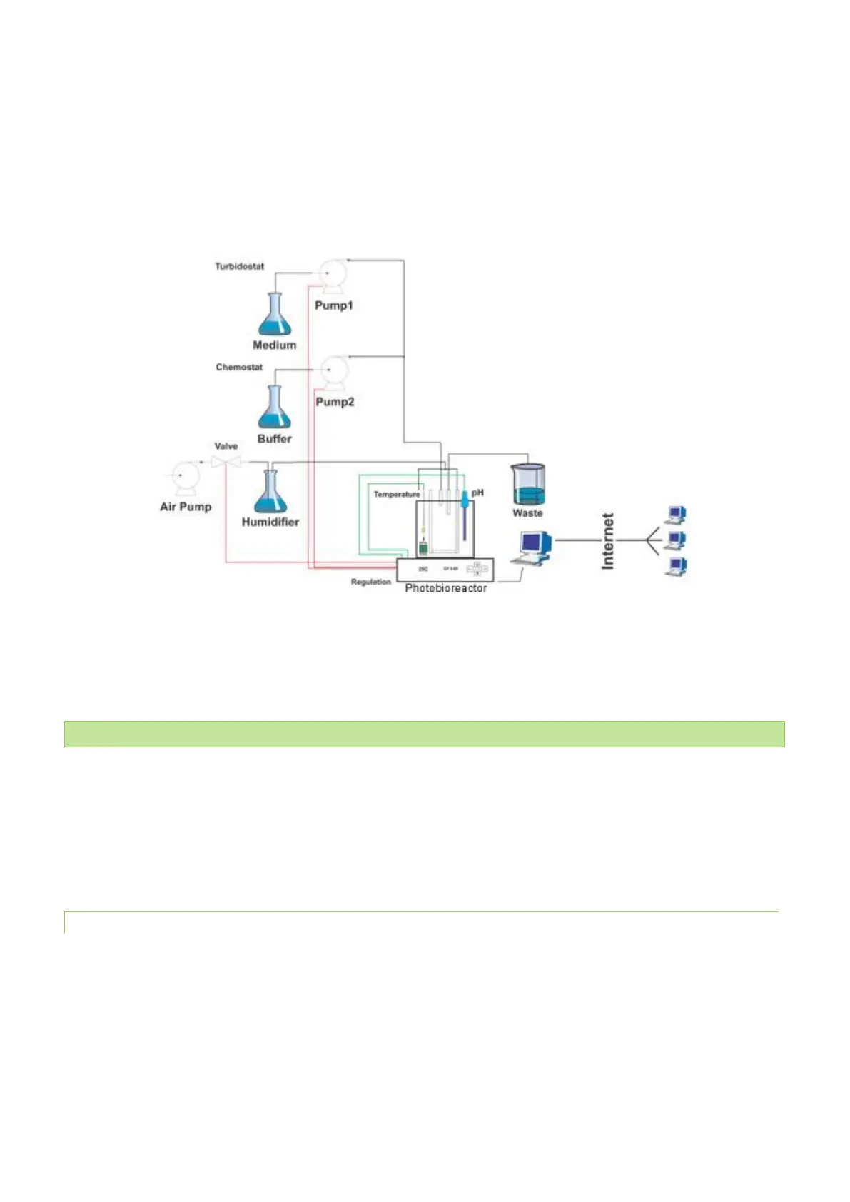
The Photobioreactor can also control external modules such as peristaltic pumps and solenoid valves via the
photobioreactor control unit (shown schematically in Fig. 1F and Fig. 2). The solenoid valves are used to switch off the gas
supply to the culture (bubbling) during optical measurements. Peristaltic pumps are used in turbidostat and chemostat
modes to supply fresh medium or buffer.
Fig. 2 Schematic diagram of the Photobioreactor, its modules and remote control.
3.1 CONFIGURATIONS AND VERSIONS
FMT150 can be shipped with various configurations of vessel capacity, light quality, light intensity and thermoregulation.
Numerous additional accessories such as various sensors can be supplied as described in chapter 5 on page 33.
Please note that this manual describes operation of two FMT150 versions (Fig. 4) - older PBR FMT150.1 and new PBR
FMT150.2.
3.1.1 CULTIVATION VESSEL
The cultivation vessel is flat and rectangular in shape. Its front and back windows are made of glass plates. The base is
made out of stainless steel and contains a thermal bridge that facilitates heat transfer between a Peltier cell in the
instrument base and the culture suspension. The lid of the vessel is easily detachable during cleaning and contains Luer
connectors for gas or medium supply tubing, waste medium exhaust or sample collection. The three larger ports
accommodate the optional temperature/pH sensor and dissolved O
2
or CO
2
probes.
The Photobioreactor FMT150 is manufactured in three vessel capacities enabling the customer to select optimal cultivation
conditions for his experiments.