© PSI (Photon Systems Instruments), spol. s r. o.
51
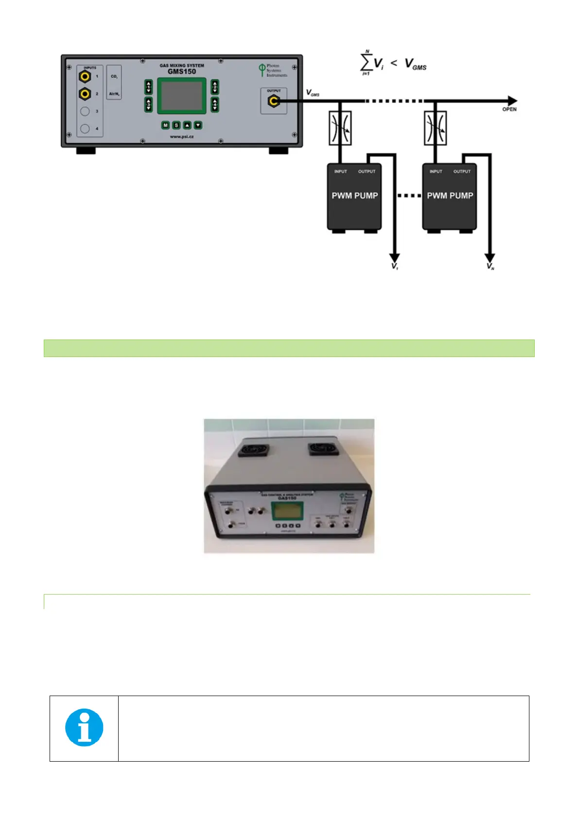
Fig. 40 Scheme for connecting more PBR FMT150 units to one GM System. V
i
refers to air flow to one PBR unit. V
GMS
refers to total air
flow output of GM unit.
5.9 GAS ANALYSIS SYSTEM GAS 150
The GAS 150 (Fig. 41) enables measurements of CO
2
with high precision at the cultivation vessel gas output (from the head
space above the culture). The GAS 150 can be used as a stand-alone gas analysis system or it can be incorporated into a
system with Photobioreactor FMT150.
Fig. 41 GAS 150.
5.9.1 INSTALLATION
Follow the instructions below to connect the Gas Analysis System 150 (GAS 150) with the PBR FMT150:
• Connect the GAS 150 with the AC power cord which is part of the accessory GAS 150 package (Fig. 42A) and plug
to electrical outlet.
• Assemble the dehumidifier as shown schematically in Fig. 42B-F and place it into the holder as shown in Fig. 42E-F.