© PSI (Photon Systems Instruments), spol. s r. o.
50
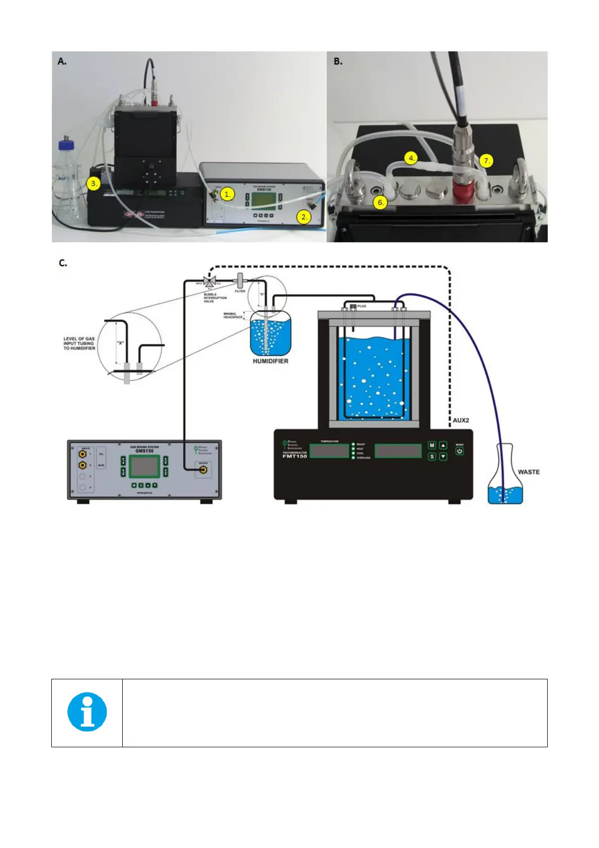
Fig. 39 GM System connection with the PBR FMT150. A) Mixed gas of given composition (1) is pumped from GM System via (2) to the
PBR FMT150 via air interruption valve (3). B) Vessel lid assembly. (4) Air distribution tube, (7) Medium outlet, (6) Sampling tube.
C) Scheme for the connection of GM with PBR FMT150.
• When more than one PBR FMT150 units are connected to the same GM system the set-up of such connection
scheme is shown in Fig. 40. For connecting more PBR FMT150 units to one GMS 150 system the customer needs
to purchase one PWM pump for each PBR FMT150 unit.
Output flow tubing from the GMS 150 should be connected with the individual PWM pumps such that the final
sum of the GMS 150 flow rate (schematically described in Fig. 40 as V
GMS
) is bigger than the sum of each PWM
pump flow rate.
Note: that the end of the output flow tubing from the GMS 150 to which the individual PWM pumps
are connected must be open to allow release of residual air from the tubing.