© PSI (Photon Systems Instruments), spol. s r. o.
52
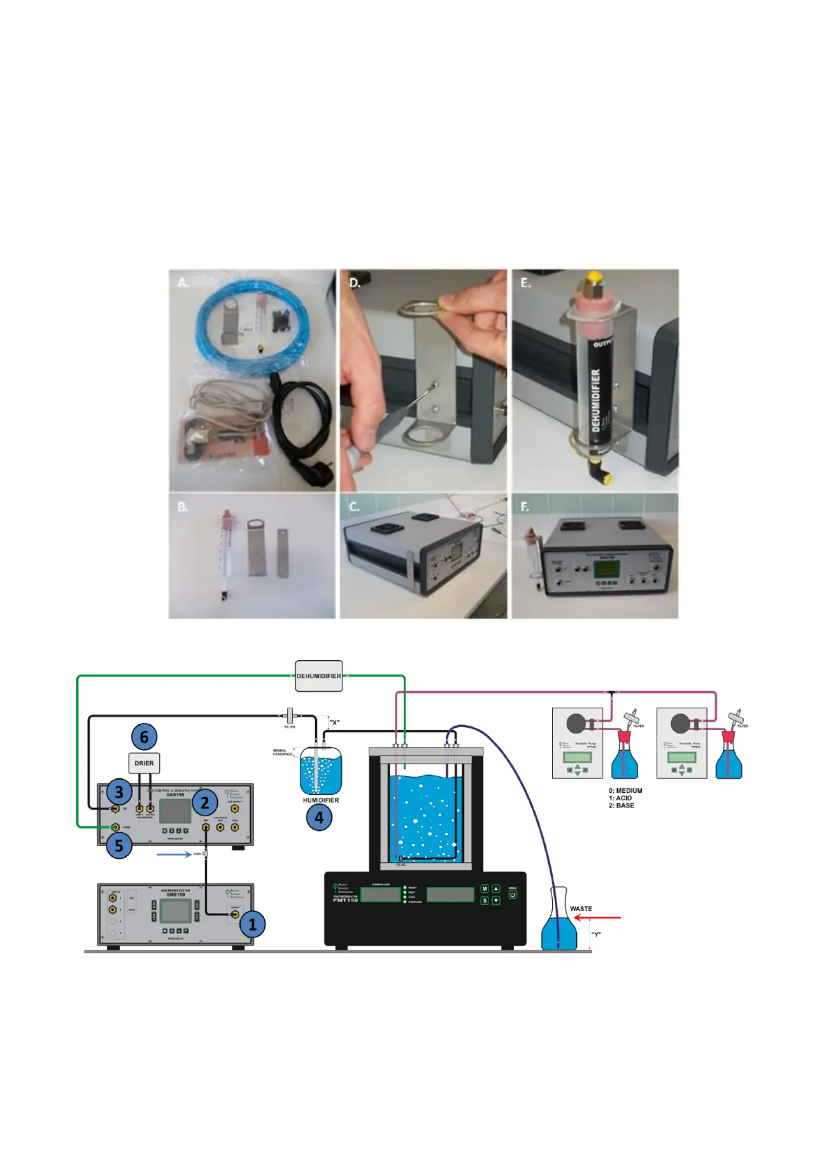
• Connect the GAS 150 to the gas source (n°2 in Fig. 43). Here the gas source comes from the Gas Mixing System
GMS 150 (n° 1).
• Connect the OUTPUT GMS tubing (n°1 in Fig. 43) with GAS input (n°2 in Fig. 43) via a T-parker connector with a
check valve (n°8 in Tab. 4) (Fig. 43 blue arrow).
• Using parker tubing and silicone tubing with Luer Lock Fittings connect Gas outlet of the GAS (n°3 in Fig. 43) via
bubble humidifier bottle (n°4 in Fig. 43) to PBR FMT150.
• Outlet from the bubble humidifier bottle is connected to the vessel lid as described previously on page 25.
Fig. 42 GAS 150 dehumidifier assembly.
Fig. 43 Schematic representation of connection scheme when GAS 150 system is connected to PBR FMT150 together with GMS 150 and
peristaltic pumps. Numbers correspond to: (1) GMS 150 output; (2) GAS 150 input for mixed air from GMS 150; (3) GAS output for
bringing the mixed air to humidifier bottle (4) and to the PBR FMT150. (5) Input for gas from the cultivation vessel to GAS 150. (6) Air
from the vessel passes through dehumidifier prior CO
2
concentration analysis.