© PSI (Photon Systems Instruments), spol. s r. o.
53
Important note: If peristaltic pump in chemostat or turbidostat mode is connected with the PBR
FMT150 together with GAS System the vessel lid configuration with the tubing assembly is different as
compared to setup with no chemostat/turbidostat module and no GAS. The set-up is shown in Fig. 44B
when standard aeration U-tube is provided.
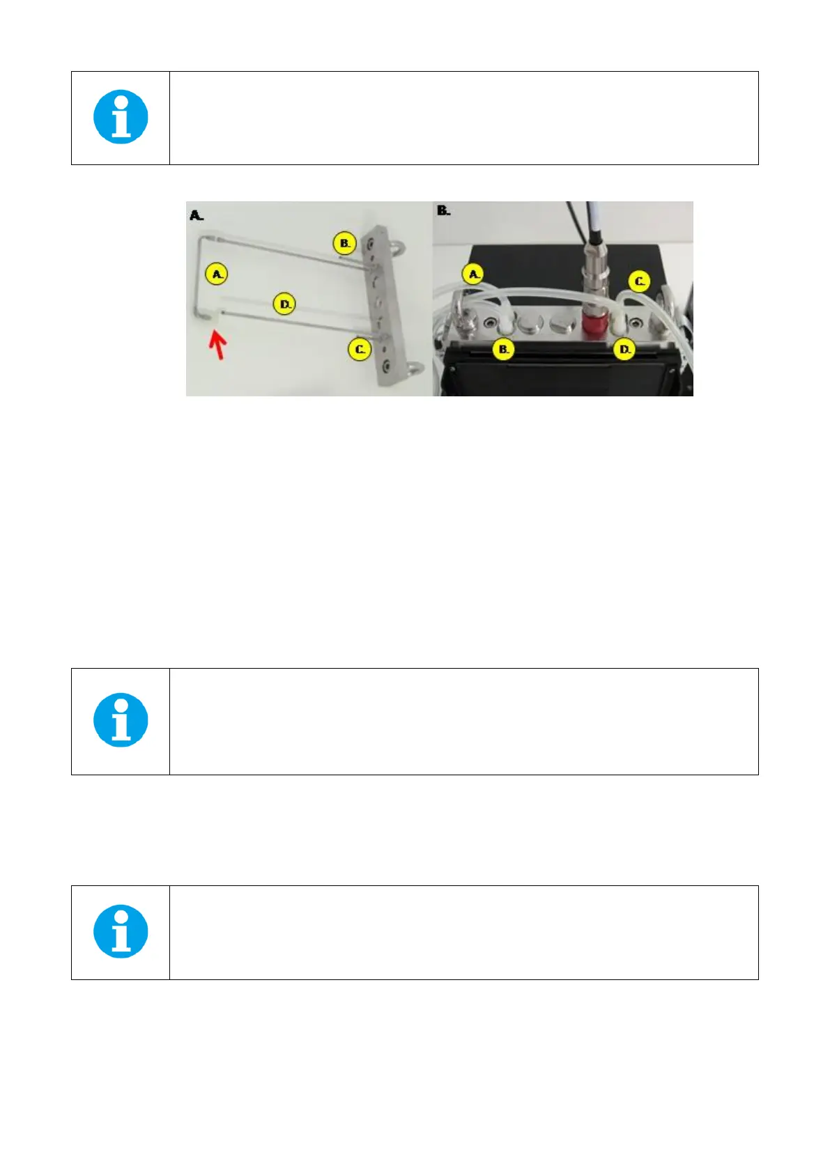
Fig. 44 Vessel lid assembly when GAS 150 system module is connected to PBR FMT150. A) Lid assembly wheb peristaltic pumps are
connected to PBR FMT150 in parallel with GAS 150 and standard aeration U-tube is used. B) Top view of vessel lid when peristaltic
pumps are connected to PBR FMT150 in parallel with GAS 150. Letters in yellow circles refer to: A-Aeration tubing; B-medium outlet;
C-gas sampling tube; D-tube for peristaltic pump connection.
Two different versions of aeration U-tube can be provided, vessel lid with standard aeration U-tubing is shown in Fig. 45A
and vessel lid with GAS aeration U-tubing is shown in Fig. 45C. In Fig. 45B standard aeration U-tubing modified for GAS
connection together with peristaltic pump as described above is shown.
If GAS 150 module is purchased both types of aeration U-tube are provided. To change the two types of aeration tubing
please follow the schematic representation of individual steps as shown in Fig. 45.
• Connect the gas outlet of the cultivation vessel via the silicone tubing (C in Fig. 44A,B) via parker tubing with the
gas inlet of the GAS (labeled FROM) (n°5 in Fig. 43).
Important note: the waste bottle for medium waste outlet (B in Fig. 44B) should be filled up to 1/3 of
its volume (red arrow in Fig. 43) with water to ensure that the air from the vessel goes always via GAS
150 and thus is not escaping through the waste tubing out of the closed system due to the pressure
imbalance.
• Switch ON the GAS System and follow the Instruction Manual for further operation of the System.
• GAS system can be operated from the GAS front panel display as described in the GAS Instruction Manual. GAS
System also can be monitored by PBR software.
Note: Please note that when using the GAS system with the PBR the bubble interruption valve is not
necessary as the GAS can perform interruption of bubbling during measurements of parameters.