© PSI (Photon Systems Instruments), spol. s r. o.
35
Important notes: O
2
electrode is made of high-quality stainless steel, grade 316, which is autoclavable.
Yet, we recommend to keep autoclaving to a reasonable minimum.
Be aware that, although the O
2
electrode is made of high-quality stainless steel, a very aggressive
growth medium can cause its corrosion. Consult your specific conditions with the electrode
manufacturer.
5.4.1 INSTALLATION
Follow these instructions to install the O
2
sensor:
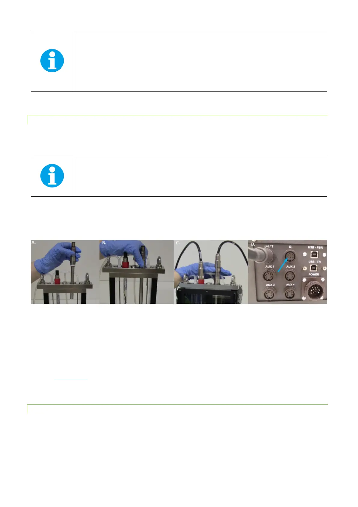
• Insert the O
2
electrode into the connector on the right side of the vessel lid and secure it tightly (Fig. 23A,B).
Note: The placement of the O
2
sensor on the right side of the vessel is recommended as it needs to be
close to the magnetic stirrer to ensure homogeneous mixing of the media and prevent localized
depletion of O
2
near the electrode.
• Attach the cable labeled “O
2
” to the electrode (Fig. 23C)
• Attach this cable to the connector at the back panel of the Photobioreactor. See the blue arrow in Fig. 23D for
FMT150.2 set up. In FMT150.1 attach it to “optional sensor” connector (see Fig. 8).
Fig. 23 Installation of the O
2
sensor. A) Positioning the electrode. B) Securing of the electrode. C) Attaching the cable to the positioned
O
2
electrode. D) Attaching the cable to the rear side of the PBR FMT150.2.
• When connected to the PBR FMT150 control unit, the sensor is automatically recognized. The function of the O
2
sensor can be controlled manually by the front panel of the control unit or by PBR software. For manual control
please refer to chapter 7.1 on page 62 for more detailed explanation.
• Before first use of the electrode we recommend to read the manual provided by the electrode manufacturer
(www.mt.com).
5.4.2 CALIBRATION
The calibration of the dissolved O2 probe can be performed with assistance of PBR software (for more details see the PBR
Software manual).