C-863.12 Mercury Controller MS249E Version: 1.2.1 265
13.3 Pin Assignment
13.3.1 Motor
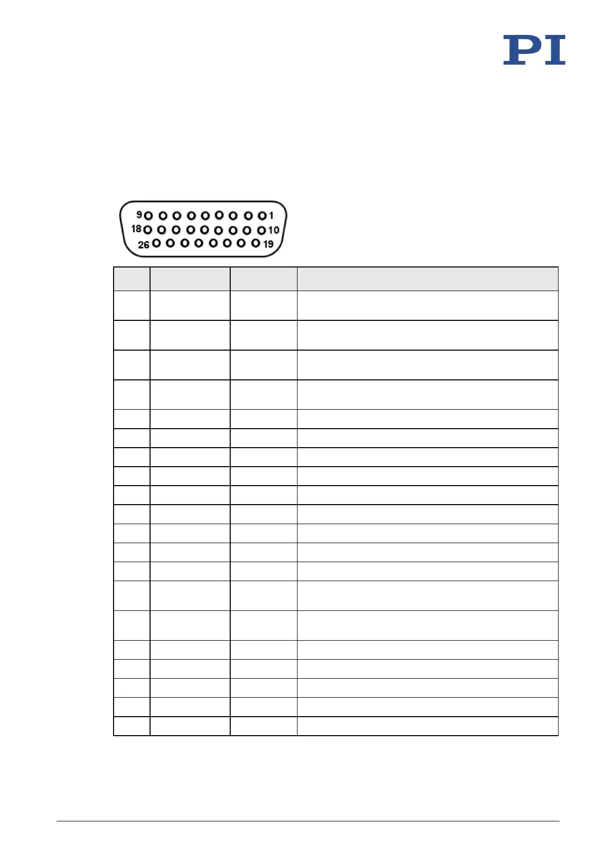
HD D-sub 26 (f)
Motor + (differential; power PWM); for positioners
without PWM amplifier
Motor + (differential; power PWM); for positioners
without PWM amplifier
Motor - (differential; power PWM); for positioners
without PWM amplifier
Motor - (differential; power PWM); for positioners
without PWM amplifier
Reference switch (5 V TTL input, single-ended)
Negative limit switch (5 V TTL input)
Positive limit switch (5 V TTL input)
PWM sign (TTL); for positioners with PWM amplifier
PWM magnitude (TTL); for positioners with PWM
amplifier
Motor brake 5 V TTL, for positioners with integrated
brake driver
Motor brake driver (0 to 48 V supply)
ID chip (intended for future use)
Position sensor power supply (5 V, 200 mA)
Encoder input A+ (RS-422)
Encoder input A- (RS-422)