24 Version: 1.2.1 MS249E C-863.12 Mercury Controller
3.5.11 Reference Switch Detection
The C-863.12 receives the signal from the reference switch at the Motor socket (p. 265).
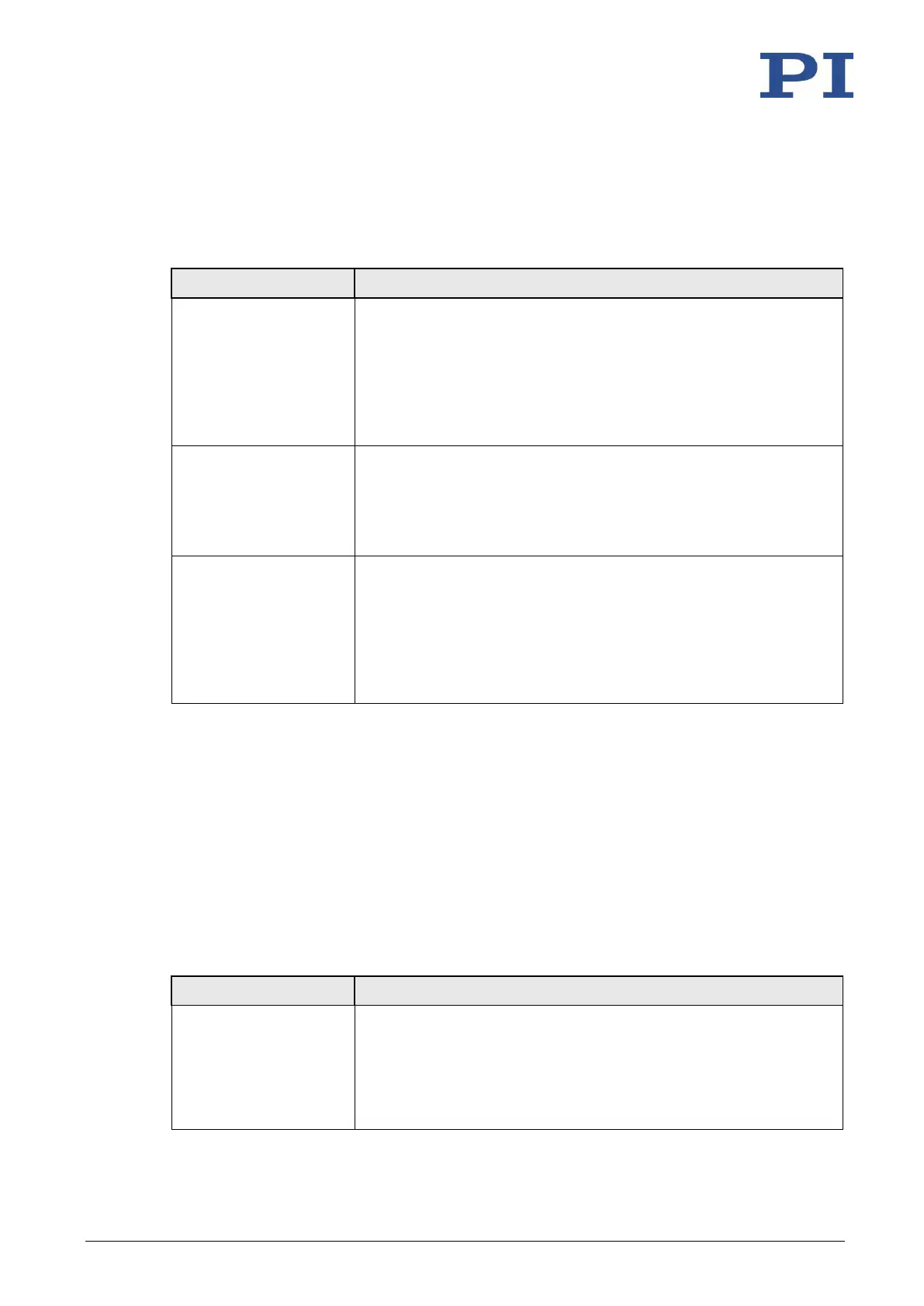
Reference switch detection by the C-863.12 can be configured with the following parameters:
Description and Possible Values
Should the reference signal be inverted?
0 = Reference signal not inverted
1 = Reference signal inverted
This parameter is used for inverting the reference signal whose
source can be either the reference switch or a digital input which is
used instead of the reference switch (p. 86).
Does the positioner have a reference switch?
0 = Reference switch not installed
1 = Reference switch available (signal input on motor connector)
This parameter activates or deactivates reference moves to the
installed reference switch.
Reference Signal Type
0x70
Reference signal type
0 = Direction-sensing reference switch (default setting). The signal
level changes when passing the reference switch.
1 = Pulse signal with a pulse width of several nanoseconds
(parameter 0x47 must be set correctly).
2 = Index pulse. The approach takes place via the negative limit
switch.
The signal from the reference switch of the positioner can be used for reference moves. After a
reference move to the reference switch, the controller knows the absolute axis position; see
"Referencing" (p. 28).
3.5.12 Limit Switch Detection
The C-863.12 receives limit switch signals at the Motor (p. 265) socket:
▪ Pin 12: Positive limit switch
▪ Pin 11: Negative limit switch
The following parameters can be used to configure how the C-863.12 detects the limit switches:
Description and Possible Values
Signal logic of the limit switches
0 = Positive limit switch active high (pos-HI), negative limit switch
active high (neg-HI)
1 = Positive limit switch active low (pos-LO), neg-HI
2 = pos-HI, neg-LO
3 = pos-LO, neg-LO