C-863.12 Mercury Controller MS249E Version: 1.2.1 77
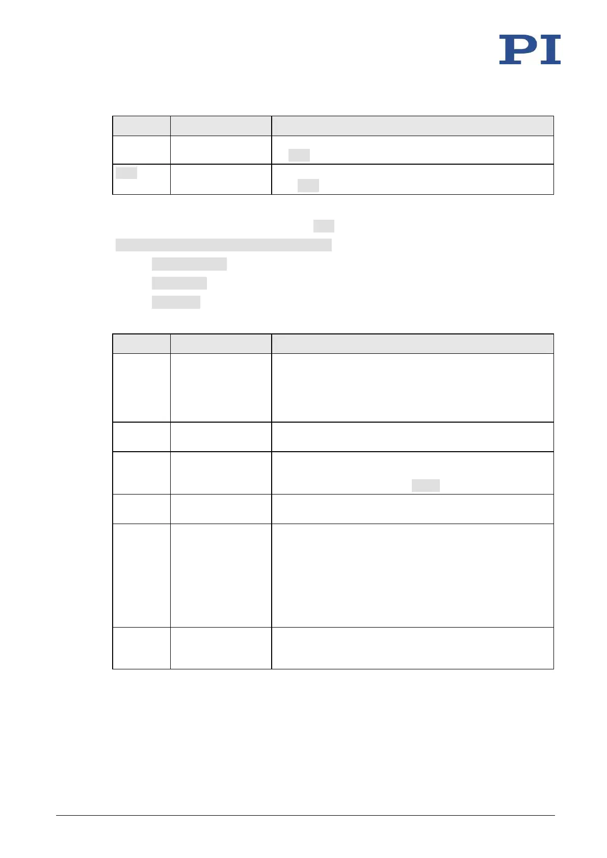
used for output lines where the trigger output is activated
by TRO.
TRO {<TrigOutID>
<TrigMode>}
Activates or deactivates the trigger output conditions set
with CTO. Default: Trigger output deactivated.
One configuration setting can be made per CTO command:
CTO <TrigOutID> <CTOPam> <Value>
▪ <TrigOutID> is one digital output line of the controller.
▪ <CTOPam> is the CTO parameter ID in decimal format.
▪ <Value> is the value to which the CTO parameter is set.
The following trigger modes (<Value>) can be set for <CTOPam> = 3:
Once the axis has moved a specified distance, a trigger pulse
is output (p. 78).
Optionally, start and stop values can be defined to limit
triggering to one position range and one particular direction
of motion (negative or positive).
The on-target state of the axis selected is output at the
selected trigger output (p. 80).
The selected digital output line becomes active when a
motion error occurs (p. 80). The line stays active until the
error code is reset to 0 (by an ERR? query).
The selected digital output line is active as long as the
selected axis is in motion (p. 80).
The first trigger pulse is output when the axis has reached a
specified position. The next trigger pulses are each output
when the axis position equals the sum of the last valid
trigger position and a specified distance. The trigger output
is stopped when a stop value is reached. The polarity sign of
the distance value determines the direction of motion in
which trigger pulses are to be output. Refer to "Configuring
the "Position + Offset" Trigger Mode" (p. 81).
The selected digital output line is active when the axis
position has reached or exceeded a specified position (p.
82).
In addition, the polarity (active high / active low) of the signal at the digital output can be set (p.
83).