C-863.12 Mercury Controller MS249E Version: 1.2.1 85
JRC <Jump>
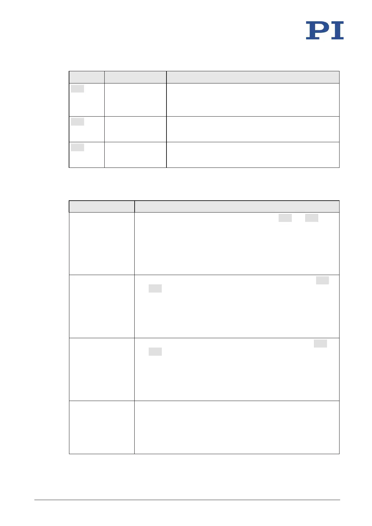
<CMD?> <OP>
<Value>
Can only be used in macros. Triggers a relative jump of the
macro run pointer depending on the state of a digital input
line when used in conjunction with the DIO? query
command.
Can only be used in macros. Stops running of the macro
depending on the state of a digital input line when used in
conjunction with the DIO? query command.
Can only be used in macros. Waits until a digital input line
reaches a certain state when used in conjunction with the
DIO? query command.
Parameters
The following parameters are available for the configuration of digital inputs:
Description and Possible Values
Source Of Reference
Signal
0x5C
Specifies the source of the reference signal for the FRF and FED
commands:
0 = reference switch
1 = Digital input 1
2 = Digital input 2
3 = Digital input 3
4 = Digital input 4
Source Of Negative
Limit Signal
0x5D
Specifies the source(s) of the negative limit switch signal for the FNL
and FED commands via a bitmask:
0 = Negative limit switch (default setting)
1 = Digital input 1 (bit 0)
2 = Digital input 2 (bit 1)
4 = Digital input 3 (bit 2)
8 = Digital input 4 (bit 3)
Source Of Positive
Limit Signal
0x5E
Specifies the source(s) of the positive limit switch signal for the FPL
and FED commands via a bitmask:
0 = Positive limit switch (default setting)
1 = Digital input 1 (bit 0)
2 = Digital input 2 (bit 1)
4 = Digital input 3 (bit 2)
8 = Digital input 4 (bit 3)
Invert Digital Input
Used For Negative
Limit
0x5F
Inverts the polarity of the digital inputs, which are used for the source
of the negative limit switch signal, via a bitmask:
0 = No digital input inverted (default setting).
1 = Digital input 1 inverted (bit 0)
2 = Digital input 2 inverted (bit 1)
4 = Digital input 3 inverted (bit 2)