56
SERIES FE
EN
LOW-PRESSURE GAS REGULATOR | INSTALLATION | REV. 00
Use, maintenance and warning manual
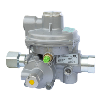
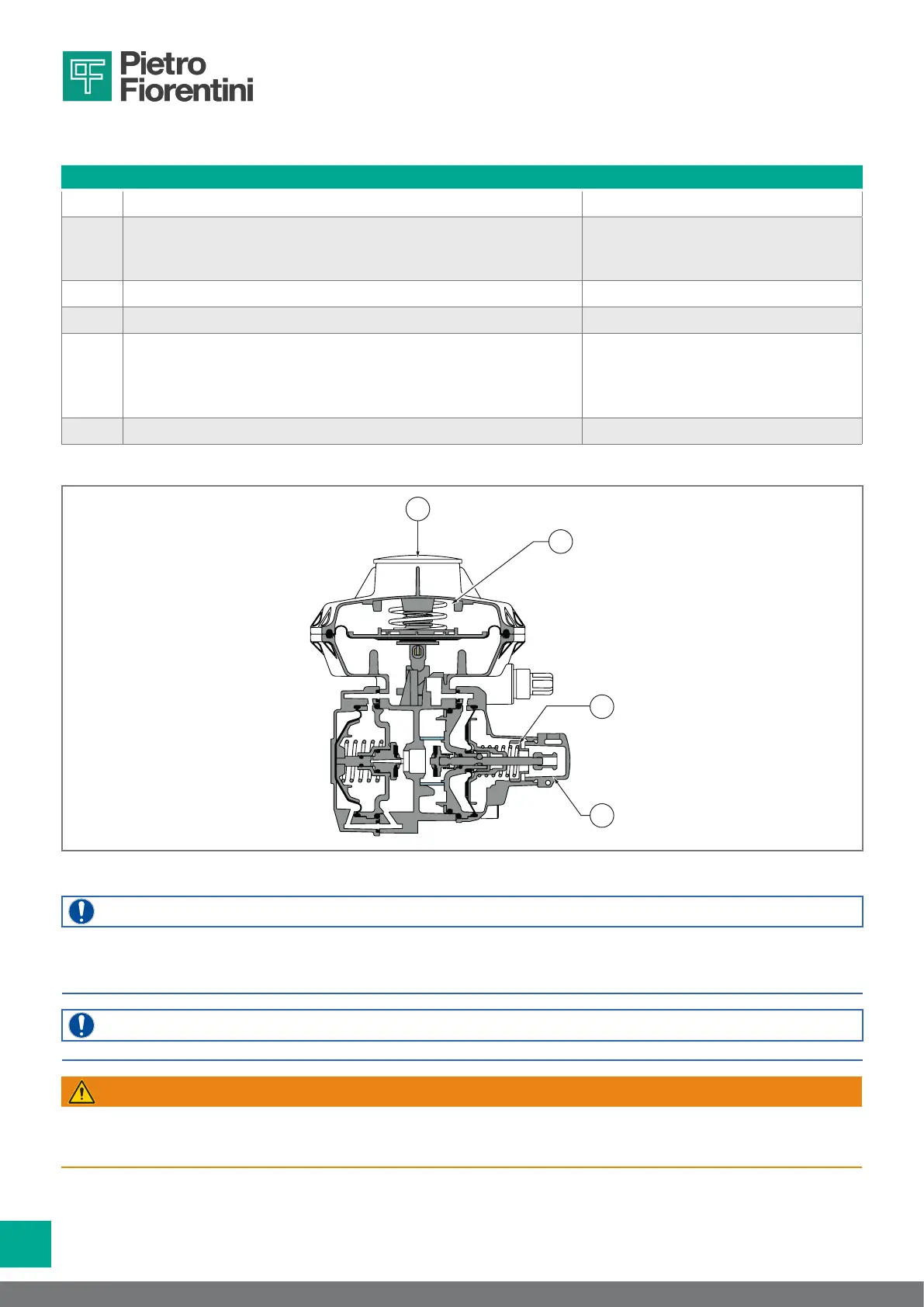
If it is necessary to change the calibration values, proceed as indicated in Tab. 6.35. to increase or decrease the operating
pressure:
Step Action Necessary equipment
1 Remove the upper cap (A) of the regulator. -
2
Turn the ring nut (B) clockwise
• to increase the downstream pressure;
• anticlockwise to decrease the downstream pressure.
27 mm tubular socket wrench
3 Put the upper cap (A) of the regulator back in place. -
4 Remove the cap of the slam-shut device (C). -
5
Turn the ring nut (D):
• clockwise to increase the slam-shut valve tripping pressure;
• anti-clockwise to decrease the slam-shut valve tripping pres-
sure.
13 mm tubular socket wrench
6 Put the cap of the slam-shut device (C) back in place. -
Tab. 6.35.
D
B
A
C
Fig. 6.11. Operating pressure regulation
NOTE!
Minimum calibration variations of ± 10% with respect to the value shown on the nameplate (see paragraph
2.8 “Identication plates applied”) can be performed only by adhering to the spring ranges specied in the
tables in chapter 10 (“Calibration tables”).
NOTE!
The relief valve pressure does not need to be adjusted.
WARNING!
Contact PIETRO FIORENTINI S.p.A. for any further need.
Do not make any unauthorised changes to the equipment without the approval of
PIETRO FIORENTINI S.p.A.
 Loading...