Function description
Operating Manual PNOZ m C0
1006013-EN-02
| 15
5 Function description
5.1 Integrated protection mechanisms
The relay meets the following safety requirements:
} The circuit is redundant with built-in self-monitoring.
} The safety device remains effective in the case of a component failure.
} The safety outputs are tested periodically using a disconnection test.
5.2 Functions
The function of the inputs and outputs on the control system depends on the user program
created using the PNOZmulti Configurator. The user program is transferred to the base unit
via chip card or via the USB port. The base unit has 2 microcontrollers that monitor each
other. They evaluate the base unit's input circuits and switch the outputs accordingly.
The LEDs on the base unit indicate the status of the configurable control system
PNOZmulti.
The online help for the PNOZmulti Configurator contains descriptions of the operating
modes and all the functions of the control system, plus connection examples.
5.3 Reaction times
t ReactionMax = t Max input delay + t Max processing time. + t Max switch-off delay at
the output
Please note that the reaction time is also increased by
} Delay times configured in the user program
} Delay on the sensor that is used
} Delay on the actuator that is used
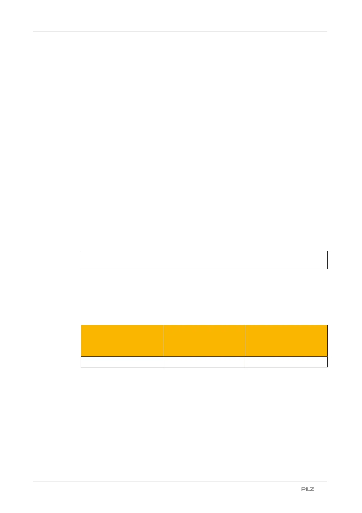
Example configuration: PNOZ m C0
Input
PNOZ m C0
Max. input delay
Processing in the user
program
Processing time
Output
PNOZ m C0
Switch-off delay
14ms 5 ms 1 ms
t
ReactionMax
= 14 ms + 5 ms + 1 ms
t
ReactionMax
= 20 ms

 Loading...


