Commissioning
Operating Manual PNOZ m C0
1006013-EN-02
| 22
7 Commissioning
7.1 General wiring guidelines
The wiring is defined in the circuit diagram in the Configurator. There you can select the in-
puts that are to perform a safety function and the outputs that are to switch this safety func-
tion.
Note:
} Information given in the Technical details [ 30] must be followed.
} Outputs O0 to O3 are semiconductor outputs
} Use copper wiring with a temperature stability of 75 °C.
} Sufficient fuse protection must be provided on all output contacts with inductive loads.
} The safety system and input circuits must always be supplied by a single power supply.
The power supply must meet the regulations for extra low voltages with protective separ-
ation (SELV/PELV).
} Do not route the test pulse cables together with actuator cables within an unprotected
sheathed cable.
7.2 Connection
Procedure:
} Wire the inputs and outputs on the base unit in accordance with the circuit diagram.
} Connect the supply voltage:
– Terminal 24 V: + 24 VDC
– 0V terminal: 0 V
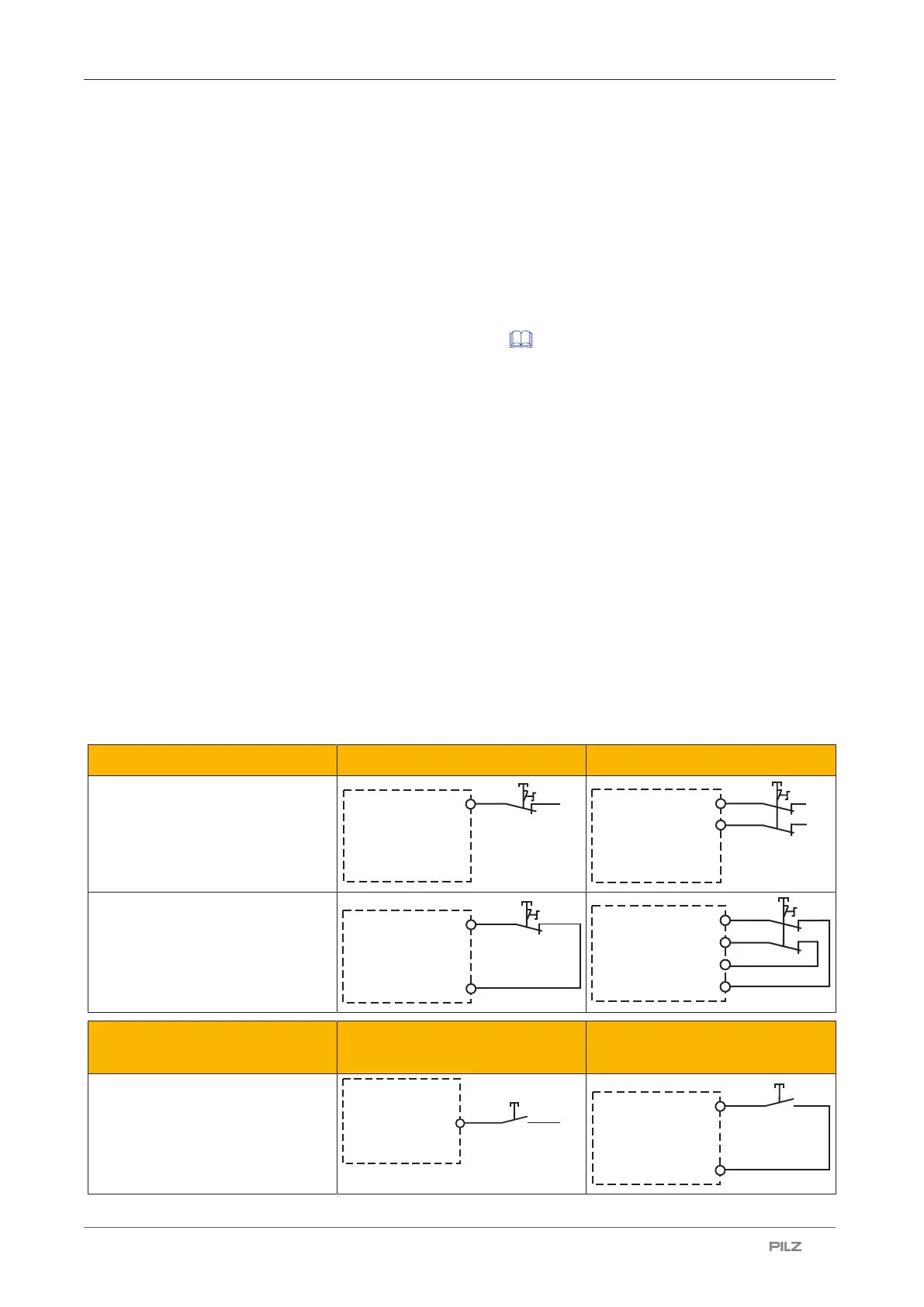
Input circuit Single-channel Dual-channel
Emergency stop
without detection of shorts across
contacts
Emergency stop
with detection of shorts across
contacts
Start circuit Input circuit without detection
of shorts across contacts
Input circuit with detection of
shorts across contacts

 Loading...


