2-13Operating Manual: PSS SB 3006-3 Series
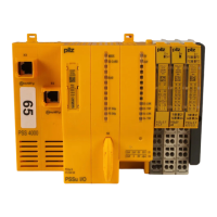
6: Programming device interface
RS 232 (minimum configuration: TxD, RxD, GND)/RS 485
7: User interface
RS 232/RS 485
8: Pushbutton for switching on and off the RS 485 termination on the
user interface
9: Supply voltage connection (24 VDC)
10: Inputs and test pulse outputs
11: Labelling strip for Ethernet address
12: ETH-2 interface with connection to ETHERNET via integrated switch
(2 free ports); LEDs on each port for
- Status of network connection (LINK)
- status of data traffic (TRAFFIC)
13: LED for status of SafetyBUS p 0
14: SafetyBUS p interface (SafetyBUS p 0)
15: LED for status of SafetyBUS p 1
16: SafetyBUS p interface (SafetyBUS p 1)
17: 2-position switch for selecting the station address
(PROFIBUS-DP)
18: Rotary switch for setting the station address (PROFIBUS-DP)
19: LED for status of PROFIBUS-DP
20: PROFIBUS DP interface
21: Functional earth connection
INFORMATION
Please refer also to the manuals: “ETH-2 for Compact 3rd Generation
PSS” and “PROFIBUS-DP for Compact 3rd Generation PSS”.
Artisan Technology Group - Quality Instrumentation ... Guaranteed | (888) 88-SOURCE | www.artisantg.com
 Loading...