73
PDP-433CMX
5
678
5
6
7
8
C
D
F
A
B
E
1. In Adjustment Item
Display color : White
Halftone : Blue (second line/15th line
for each 1st to 32th columns)
When the input signal mode is not identified, the
adjustment value is displayed with
"––––––" (–––––––)", and the item indication is grayed.
• Second line / 2nd to 12th columns : Display the higher layer of selection item • • • In Service Factory mode
Second line / 2nd to 3rd columns : Display the ID No. • • • In RS-232C Factory mode
Second line / 5th to 12th columns : Display the higher layer of selection item • • • In RS-232C Factory mode
• Second line / 15th to 16th columns : Current color mode setting
• Second line / 18th to 19th columns : Current slot type
• Second line / 21th to 23th columns : Current function
• Second line / 25th to 28th columns : Current signal mode
• Second line / 28th columns : Current Screen size (See "Classification of input signal" for details in each value.)
• Second line / 29th column : Current input form
Input Form Component Video–RGB Composite Y/C
Display # @ ∗ /
Non-display (blank) excepting above form.
• Second line / 30th to 31th columns : Current color system
• 15th line / 2nd to 20th columns : Current item selection
• 15th line / 22th to 31th columns :
When RANGE CHECK is selected: Current selecting value
1. When REFERENCE is selected : Adjustment value
2. When OFFSET is selected : OFFSET value (adjustment value) * Adjustment value is REFERENCE value + OFFSET value.
3. When VIDEO OPTION is selected : No display
When INITIALIZE is selected : Selected setting. (No display for an item having the lower layer.)
Color System NTSC PAL SECAM 4.43NTSC PAL-M PAL-N BLACK/WHITE
Display NT PL SC 4N PM PN BW
Non-display (blank) in a case of a color system other than those mentioned above or when the COLOR SYSTEM setting is fixed.
Setting Signal Mode Display
VIDEO 03
VGA 31
WVGA E1
XGA 61
WXGA 71
Display in the no signal and incompatible signal
Signal mode displays for mode 03, mode 31, mode E1, mode 61 or mode 71
Signal mode displays for mode 12 or mode 13
HDTV Mode Setting (Integrator Menu) Signal Mode Display
1080i 12
1035i 13
Signal Mode Display Signal Definition
FB OUT OF RANGE (Signal that cannot be measured with the main microcomputer)
FC OUT OF RANGE (Video system signal without video signal)
FD OUT OF RANGE (Incompatible signal at DVI input)
FE
OUT OF RANGE (Incompatible signal that is measurable with the main microcomputer, and not applicable to FC and FD)
FF
No signal
Slot Type or
Model Type
PDA-5002
PDP-503PRO
and PRO-1000HD
Slot Manufactured
by Other Vender
No SLOT
Display S1 US T1 to T8 NO
OF S–––S1 I N4– 0
():
2 – ∗
∗∗∗
∗∗∗
2NTSLOT
Y – DELAY
#1
1
5
10
15
16
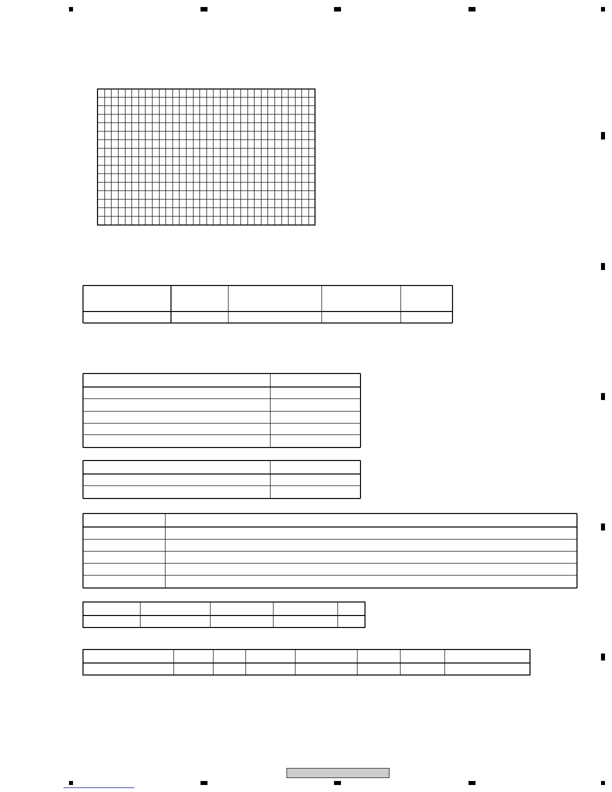
1 5 10 15 20 25 30 32
6.1.3 DESCRIPTION OF SERVICE FACTORY MENU DISPLAY
 Loading...