185
RS-232C Adjustment Mode
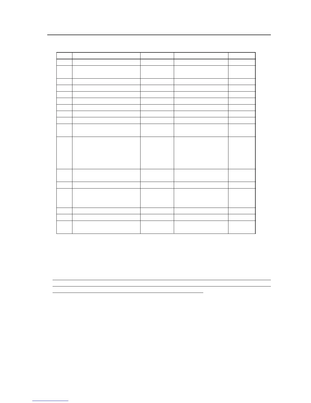
4) <GSO> (GET STATUS OPTION) Set data for OPTION will be output as follows.
Order Data Size Output Remarks
1 POWER CONTROL 3byte
Same as RS-232C command
2 OSD display 1byte 0: OSD display disabled
1: OSD display enabled
3 FULL MASK 3byte
Same as RS-232C command
4 R SIDE MASK LEVEL 3byte Adjustment value
5 G SIDE MASK LEVEL 3byte Adjustment value
6 B SIDE MASK LEVEL 3byte Adjustment value
7 MASK CONTROL 1byte 0: Fixed, 1: Shifts
8 ORBITER MODE 1byte 0: OFF, 1: ON
9 INVERSE MODE 1byte 0: OFF, 1: ON
10 COLOR MODE 1byte 1: COLOR MODE1
2: COLOR MODE2
11 MIRROR MODE 1byte X: Left-right reversal
Y: Top-bottom reversal
Z: Top-bottom and
left-right reversal
N: OFF
12 FAN CONTROL 1byte A: AUTO
M: MAX
13 MONITOR NAME 12byte
14 SLOT INPUT 1byte 0: VIDEO (RGB)
1: COMPONENT1
2: COMPONENT2 (NOTE)
15 TEMPERATURE 3byte
16 HOUR METER 5byte
17 KEY LOCK 1byte 0: Lock released
1: Lock applied
(NOTE) Dummy data will be output when the PDA-5002 is connected.
TEMPERATURE (3 bytes)/2 + 5 = Outside air temperature (°C) sensor value
(NOTE) Control the above sensor value so it does not exceed the values shown below.
PDP-503CMX/PDP-503MXE: 45
PDP-433CMX/PDP-433MXE: 53
When installing it, measure the surrounding temperature to make sure that all conditions stipulated in
surrounding temperature conditions in “3. Installation Environment” are satisfied. Be particularly sure to
confirm this when installing it as stipulated in 3.5, 3.6 Special Installation.
 Loading...