PDP-507XD
184
1234
1234
C
D
F
A
B
E
FAN_CONT_POW
TEMP2
FAN_NG1 (H act)
V+3V_COM
TEMP2
FAN_12V
Drive
Circuit
PULL_U
PULL_U
SENSOR
FAN_CONT
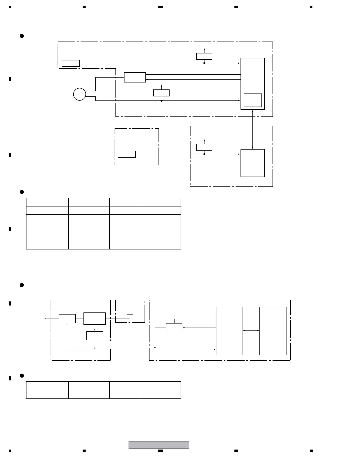
Fan and temperature sensor
Circuit diagram
DTB antenna power supply
Circuit diagram
Specifications for port monitoring
MAIN Assy
SENSOR Assy
DIGITAL Assy
MAIN_UCOM
FAN_NG
Detection
Logic
FAN
1
Port Name SD/PD Indication Assigned Pin Active
FAN_NG 1 FAN Shutdown with H
TEMP2
Abnormally high
temperature in the
MR
Shutdown when the
value exceeds the
predetermined value
TEMP0
Abnormally high
temperature in the
Drive circuit
Shutdown when the
value exceeds the
predetermined value
Specifications for port monitoring
Port Name SD/PD Indication Assigned Pin Active
ANT_POW_EU DTB antenna short IF_37 Warning with L
V+3V_COM
TEMP2
TEMP0
PULL_U
SENSOR
MODULE_
UCOM
V+3V_COM
Inverter
Latch
ON/OFF
Overcurrent
Detection
ANT_POW_B
H: OFF
L: ON
Monitoring
H: ON
L: OFF
ANT
IF_UCOM
ANT_POW_EU
MAIN Assy
R07 DT Assy
POWER
SUPPLY
Unit
MAIN_UCOM
V+3.3V_STB
V+5.1V_STB
Hold "L" at
the short-circuit.

 Loading...