PDP-507XD
93
5678
56
7
8
C
D
F
A
B
E
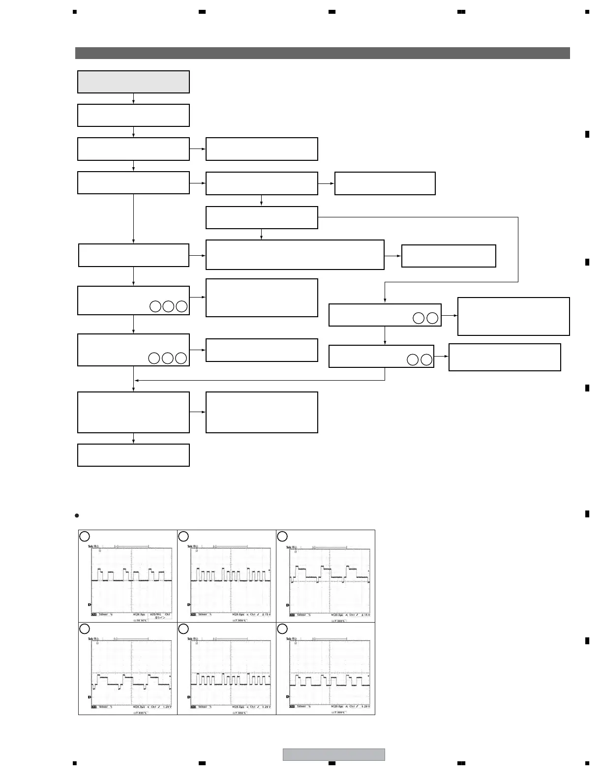
Flowchart of Failure Analysis for The Video System
No
No
Yes
Yes
Yes
Is the function correspondeing to
selected signal input selected?
Image for the RGB input signal
is not displasyed.
Select the corresponding signal
with the Input selector.
Is the screen of main side
Analog/Digital TV?
No
Has the signal arrived at IC4701?
No
Specifications that does not
display in the sub-side.
⇒ RGB
Sub
Main
Which signal is not output,
main or sub signal?
Check the circuit between IC4901 and
IC5101 and replace broken parts.
No
Check around the IC that is found to
have failure in communication and
the microcomputer. If there was no
ploblem, replace the MAIN Assy.
No
No
Check around IC4901 and check the
communications between IC4901
and microcomuputer. If there was
no ploblem, replace the MAIN Assy.
No
Check around IC4701 and check the
communications between IC4701
and microcomuputer. If there was
no ploblem, replace the MAIN Assy.
No
Replace the MAIN Assy.
Is a signal output from IC4901?
(pins 30, 32 and 34)
Has the signal arrived at IC5101?
(pins 160, 164 and 172)
Yes
Yes
Is the communication between
each IC (VDEC, ASIC) on the
MAIN Assy and the microcomputer
normal?
Yes
Yes
Has the signal arrived at
IC5103? (pins 1 and 2)
Has the signal arrived at IC4901?
Yes
Yes
Yes
212019
Is a signal output from
IC4701? (pins 47 and 49)
12 13
14 15
1716 18
16
IC4901 - pin 30
V: 500 mV/div H: 20 µS/div
17 18
IC4901 - pin 34
V: 500 mV/div H: 20 µS/div
19
IC5101 - pin 160
V: 500 mV/div H: 20 µS/div
20
IC5101 - pin 164
V: 500 mV/div H: 20 µS/div
21
IC5101 - pin 172
V: 500 mV/div H: 20 µS/div
Waveforms
Input signal: PAL Color-bar (S terminal)
IC4901 - pin 32
V: 500 mV/div H: 20 µS/div
Check the flexible cables between the CN8802 and
CN4004 or between CN9003 and CN4005 or around
of input terminals.
No
Replace the FFCs or cables.
Check the emitter-follower circuit
between IC4701 and IC5103 and
repair the failure points.
 Loading...