ENGLISH
14
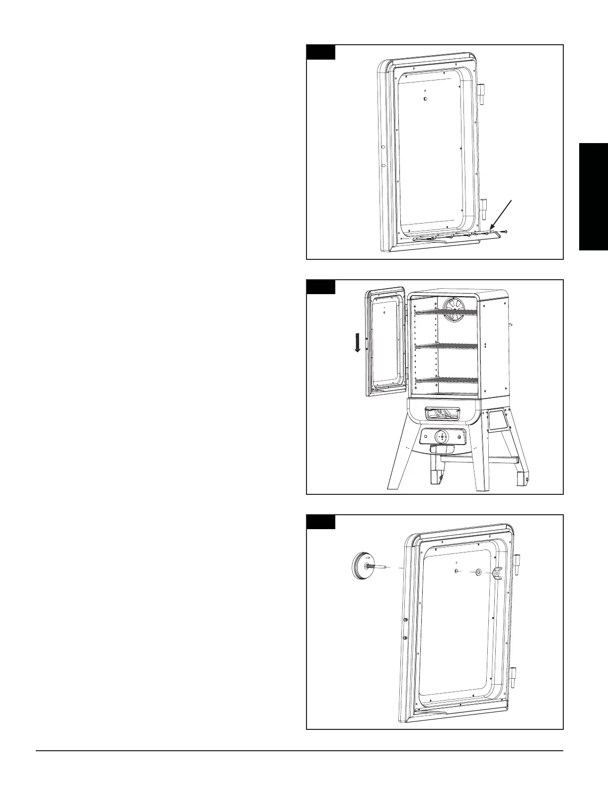
Fig.14
13.
Parts Required:
1 x Door Grease Shield (#25)
1 x Door Assembly (#7)
5 x #8-32 Self-Tapping Screw (#F)
Installation:
• Attach the Door Grease Shield (#25) to the
Door Assembly (#7) using 5 x #8-32 Self-
tapping Screw (#F) as Fig.13 shown.
14.
Parts Required:
1 x Door Assembly (#7)
1 x Upper Smoker Cabinet Assembly (#2)
Installation:
• Attach Door Assembly (#7) into the Upper
Smoker Cabinet Assembly (#2) as Fig.14 shown.
15.
Parts Required:
1 x Door Assembly (#7)
1 x Heat Indicator (#6)
Note: The Heat Indicator is supplied with one fiber washer and
one wing nut
Installation:
• Insert Heat Indicator (#6) probe through
the mounting hole in the front of the Door
Assembly (#7). From the inside of the door,
place fiber washer and wing nut onto the
mounting thread pole and tighten by hand as
Fig.15 shown.
Fig.13
25
Fig.15
6

 Loading...