ATLAS 23 of 44 User’s Manual
When "Disabled" is selected, all iPMs are on
and will evenly source the required DC output
current. When "Enabled" is selected, the
minimum number of iPMs will be on to source
the required DC output current.
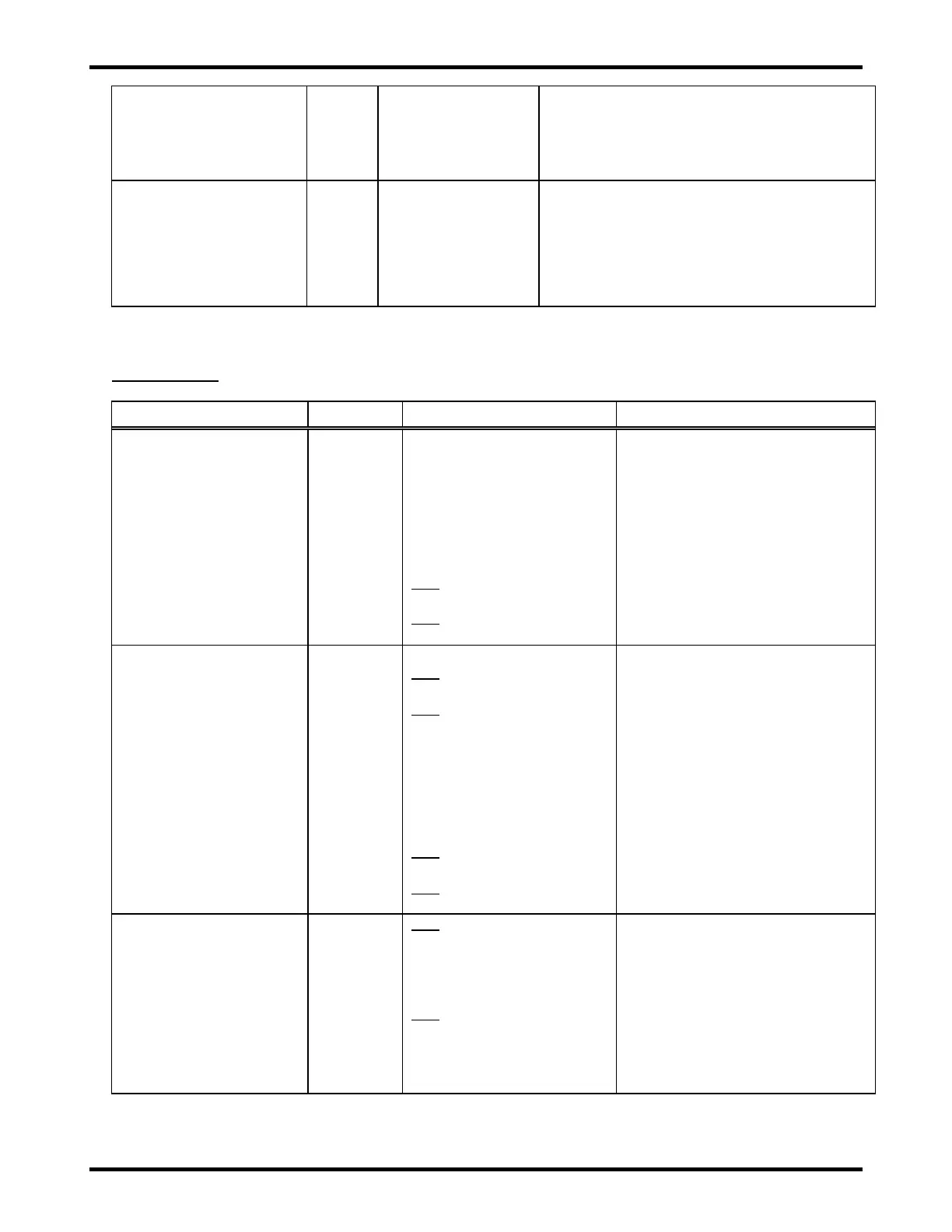
Confirm Local Presence
Time
The amount of time in minutes that web
server changes can be made after the
"CONFIRM LOCAL PRESENCE" button has
been physically pressed on the UIM. After
this time has expired, the "Confirm Local
Presence" button must be pressed again to
make additional web server changes.
11.3. Configuration >> Charge Settings
Charge Profile
Setting ranges:
1.00-3.00
The charger will limit the
total float voltage of the
battery pack (“Float Voltage
per Cell” * “Number of
Cells”) to these ranges:
12V
1.00-20.00
24V
10.00-40.00
The float voltage per cell for the
battery pack. Disabled (grayed
out) when the "NUMBER OF
CELLS" rotary switches on the
UIM are set to anything other than
"00".
Setting ranges:
12V
1-13
24V
5-26
The charger will limit the
total float voltage of the
battery pack (“Float Voltage
per Cell” * “Number of
Cells”) to these ranges:
12V
1.00-20.00
24V
10.00-40.00
The number of cells in the battery
pack. Disabled (grayed out) when
the "NUMBER OF CELLS" rotary
switches on the UIM are set to
anything other than "00".
12V
0.0-80.0 (4 iPMs)
0.0-60.0 (3 iPMs)
0.0-40.0 (2 iPMs)
0.0-20.0 (1 iPM)
24V
0.0-40.0 (4 iPMs)
0.0-30.0 (3 iPMs)
0.0-20.0 (2 iPMs)
0.0-10.0 (1 iPM)
Used to limit the DC output
current. This setting is the total
system DC output current.