5-12 888-2408-002
WARNING: Disconnect primary power prior to servicing.
Maintenance and Alignment
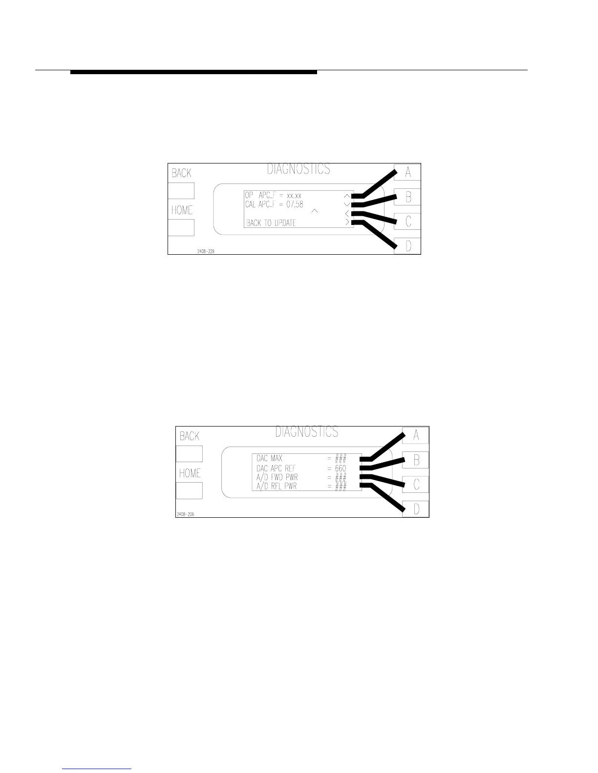
STEP 5 Press [HOME,MORE,CONFIGURATION C,A,D,C] to go to the
APC Factor screen in Figure 5-4. Set the CAL_APC_FACTOR to
7.58. To access the edit controls press and hold the [D] key and press
[C]. Press [BACK] to save the changes.
Figure 5-4 APC Calibration Factor Screen
[HOME,MORE,CONFIGURATION C,A,D,C]
STEP 6 Set R127 on the Life Support Board maximum CW.
STEP 7 Turn the transmitter on. Make sure the exciter power is on and un-
muted.
STEP 8 Press [HOME, MORE, CONFIGURATION C,B]. This will take you
to the screen shown in Figure 5-5. Using the Raise and Lower
buttons, set the DAC_APC_REF to 660.
Figure 5-5 A/D FWD PWR Screen
[HOME, MORE, CONFIGURATION C,B]
STEP 9 Re-Adjust R127 on the Life Support Board until the external meter
reads 5kW or the TPO at which you are calibrating. The adjustment
will be sensitive, so be careful not to go too fast.