6-10 888-2408-002
WARNING: Disconnect primary power prior to servicing.
Troubleshooting
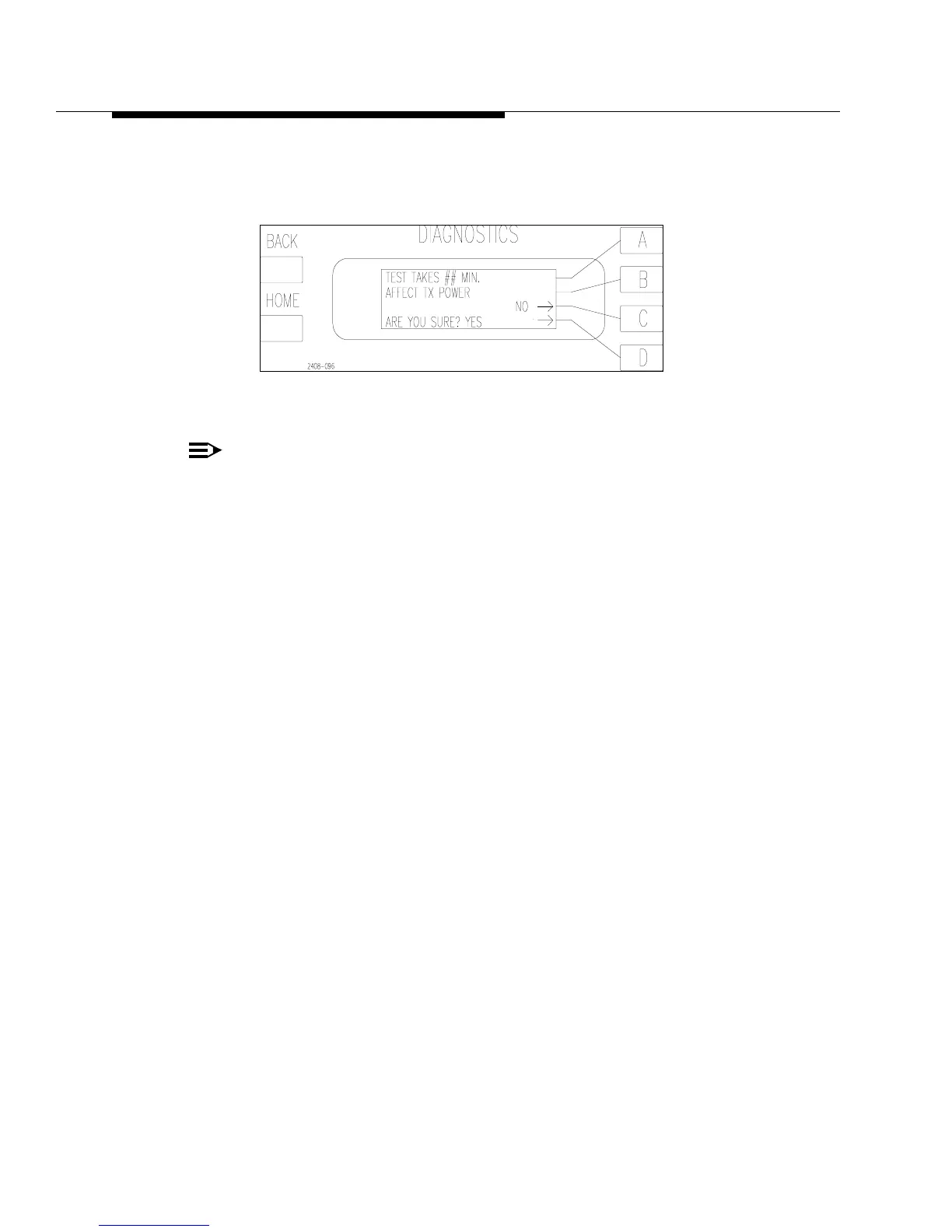
To run the SYSTEM test press [MORE TEST C]. This will bring up the screen in
Figure 6-5. Press [D] to run the test or [C] to go back to the previous menu.
Figure 6-5 System Test Screen
NOTE:
Due to operational variables, it is possible to get false indications which place
a fault in the log and abort the test. If the System Test fails, note the fault in
the Fault Log, clear the fault log, and run the test again to verify the problem.
This test should be used as part of a routine maintenance program at least once a
year. It should also be done if major combiner components are removed and/or
replaced, such as a Z-Plane or Isolation Board or if cabling is disconnected and re-
connected to the Z-Planes or Isolation Boards.
The following sequence of tests make up the SYSTEM TEST:
• PA Muting Test
• PA ISO Resistor and Thermistor Test
• PA RF Switch Test
6.7.1.1 PA Muting Test
Each PA will be muted for 1 second, one at a time. The controller then checks the
current draw of each PA, which should be close to zero. If it finds a PA that is
drawing too much current while it is supposed to be muted it will abort the test and
report an A#_MUTE_FLT or B#_MUTE_FLT. For more information refer to PA
MUTE Faults later in this Section.
6.7.1.2 PA_ISO Resistor and Thermistor Test
If the PA Muting Test is passed, the PA_ISO resistors and thermistors will be
checked. The first two tests are actually done at the same time. With the PA muted,
the ISO resistor temperature for that PA should increase within a few seconds. If it
does not the test will be aborted and an A#_ISO_LOW or B#_ISO_LOW will be
reported to the Fault Log. This could indicate one of four main possibilities.