2-6 888-2408-002
WARNING: Disconnect primary power prior to servicing.
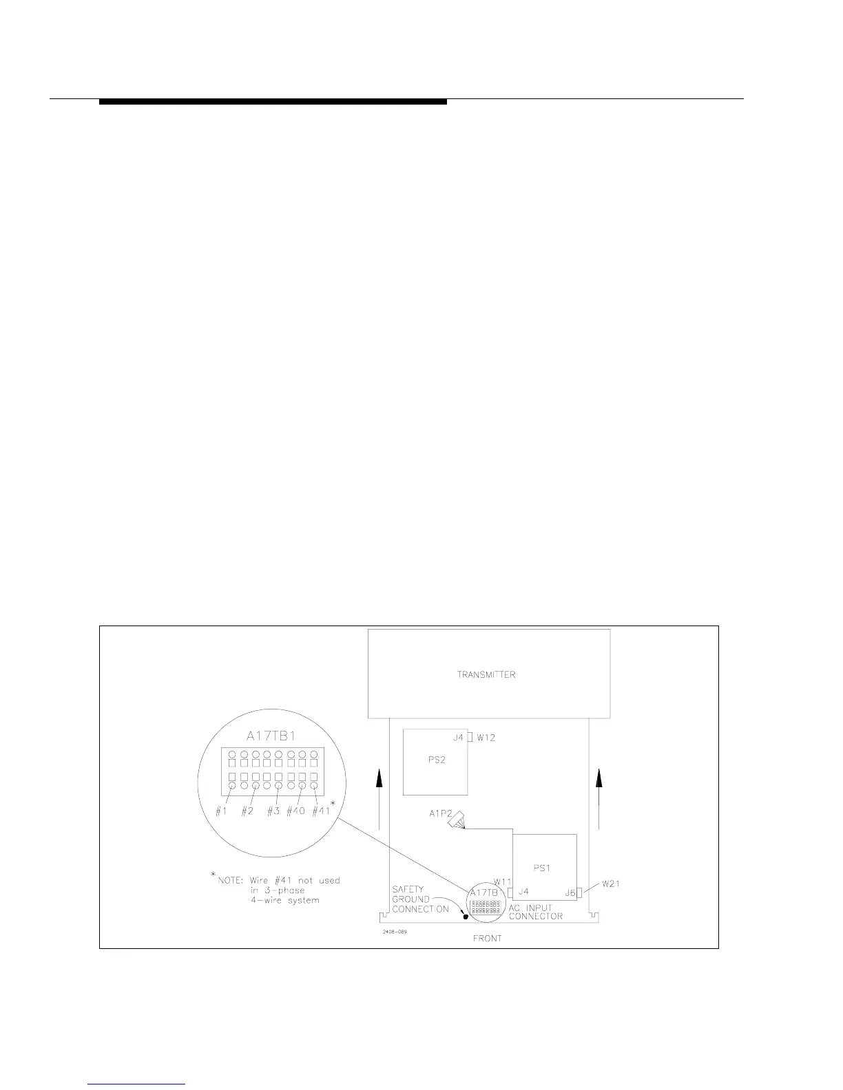
Installation & Initial Turn-On
2.5.4.2 Power Supply Connections
First, remove the front cover panel from the power supply compartment at the
bottom of the transmitter. The power supply connection cables are either tied up in
the power supply compartment (in the bottom of the transmitter) or tied up with the
power transformers. The power supply should be rolled into position in front of the
transmitter. Do not roll it in yet. There are two separate supplies on the tray, PS1 is
in front and PS2 is in the rear. The following cables will need to be connected:
a. There are two ribbon cables W11 and W12 (blue) and one control voltage
cable W21 (gray with orange connector) hanging on the right side of the
power supply compartment.
1. First connect W12 to J4 on the PS2 Rectifier Board. See Figure 2-1.
2. Now the supply can be rolled into the cabinet. Be sure to get the orange
AC input cables, #1, #2 and #3 and wires #40 and #41 out of the way
before rolling the power supply all of the way in. These are bundled on
the left side of the power supply compartment.
3. Connect W11 to J4 on the PS1 Rectifier Board.
4. Connect W21 (flat gray cable with orange connector) to J6 on the PS1
Rectifier Board.
b. The cable labeled A1P2 (gray multi-conductor cable with 12 pin gray connector)
plugs into its mating connector on the left wall of the power supply compartment.
c. Roll the power supply the rest of the way into the cabinet.
Figure 2-1 3-Phase Power Supply Top View