888-2408-002 2-7
WARNING: Disconnect primary power prior to servicing.
Installation & Initial Turn-On
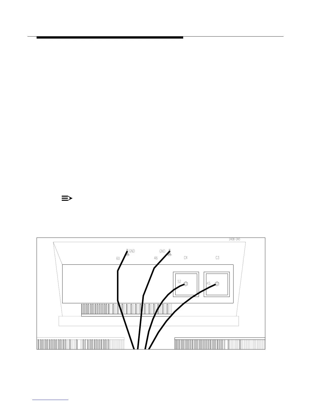
d. Wires 45 and 52 (large orange cables tied up with the transformers) connect to
the feed-thru terminals, C3 and C4 at the top of the power supply compart-
ment. These are the 52Vdc outputs from the two supplies. See Figure 2-2. The
wires connect as follows:
• Wire #52 connects to C4 (on the left along with wire #81)
• Wire #45 connects to C3 (on the right along with wire #80)
e. Wires #1, #2, and #3 (orange cables tied up on the left side of the power sup-
ply compartment) and two smaller gray wires #40 and #41* plug into the gray
Wego block connector, A17TB1 on the front of the power supply tray (A17
designates a component on the power supply tray). See Figure 2-1. The Wego
block has 8 terminals labeled terminal #1 on the left and #8 on the right. The
connections are as follows:
• Wire #1 connects to terminal #1
• Wire #2 connects to terminal #3
• Wire #3 connects to terminal #5
• Wire #40 connects to terminal #7
• Wire #41* connects to terminal #8
(*Wire #41 is not used on 3 phase 4-wire system)
NOTE:
If these wires are not connected to the appropriate terminal on the
Wego block, as designated on the Overall System Block Diagram, the
blower may not operate.
Figure 2-2 DC and Ground Connections for 3-Phase Power Supply