4-18 888-2408-002
WARNING: Disconnect primary power prior to servicing.
Overall System Theory
4.4.1.2 Single Phase Power Supply
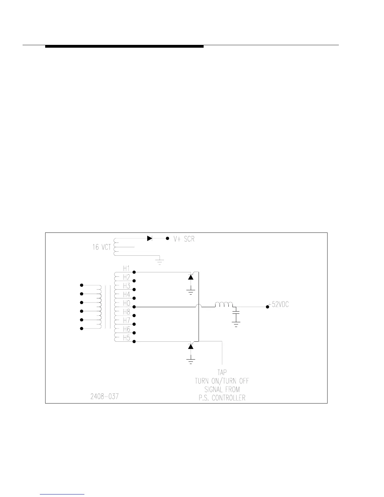
Refer to the Overall System Block Diagram in the schematic package and Figure 4-
9 for the following discussion. The power supply consists of two power
transformers each with a single center tapped secondary. The center tap is the
52Vdc output and is filtered by a large choke and 3 large filter capacitors. The
single phase supply is full wave rectified giving a ripple frequency of 120Hz and
therefore requires more filtering than the 3-Phase supply.
Each of the secondary windings has 4 output taps, each of which are connected
through an SCR to ground. The SCRs act as both tap switches, activating the tap
which gives the appropriate DC voltage output, and as rectifiers. This gives a total
of 8 SCRs per secondary, only 2 of which will be activated at any one time
providing the ability to regulate the output DC voltage by changing the transformer
turns ratio. The 4 secondary taps allow DC outputs of 48, 50, 52 and 54Vdc. The tap
switching is controlled by the Power Supply Controller board. The two transformer
assemblies are designated PS1 and PS2. PS1 provides power for 8 of the 16 PAs.
Four of these are on Z Plane A and four on Z Plane B. Therefore PS 2 provides
power for the remaining 8 PAs.
Figure 4-9 Single Phase Power Supply
Simplified Diagram