2-24 888-2408-002
WARNING: Disconnect primary power prior to servicing.
Installation & Initial Turn-On
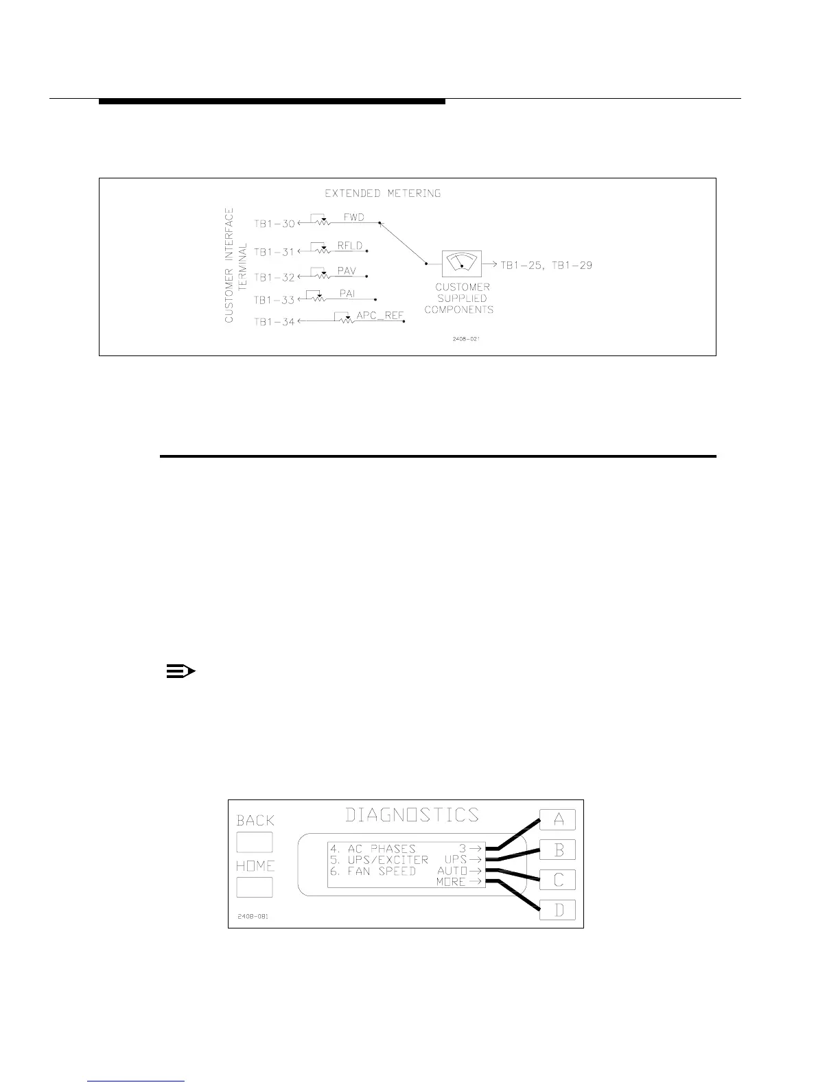
Extended metering can also be connected to TB1 terminals. See Figure 2-13 for an
example of extended metering connections.
Figure 2-13 Extended Metering
2.6 UPS IN/Remote Exciter Select,
Configurable Input TB1-9
The remote input at TB1-9 is a software configurable input which is set via the
Diagnostics Display Menu. It can be used as either a UPS Mode select input or as a
Remote Exciter select when a second exciter is installed in the transmitter. To
configure the input using the Diagnostics Display Menu press [HOME, MORE,
CONFIGURATION A,D]. This should bring up the screen shown in Figure 2-14.
The default setting is shown as “UPS”. This means the input is ready to be used as
the UPS Mode select. To use TB1-9 as a Remote Exciter Select input press [B]. This
will toggle the display to read “EXC”. This re-configures the TB1-9 input so that
when it is pulsed low momentarily, the transmitter will switch to the other exciter.
NOTE:
This input is simply a switch command and does not care which
exciter was on the air to begin with. For example, if the Main exciter is
on the air, then it will switch to the alternate, but if the alternate is on
the air it will switch to the main exciter.
Figure 2-14 Configurable Input Select
[HOME, MORE, CONFIGURATION A,D]